Rotor emf and Equivalent Circuit
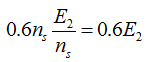
Let the rotor e.m.f. at standstill be E2 . When the rotor speed is 0.4 ns, the slip is 0.6 and the relative speed between rotating field and rotor conductors is 0.6ns. Hence, the induced e.m.f. , per phase, in the rotor is
 |
(12) |
In general, for any value of slip s, the per phase induced e.m.f in the rotor conductors is equal to sE2 . The other quantities of the rotor are given as
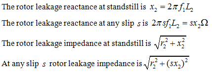 |
(13a) (13b) (13c) (13d) |
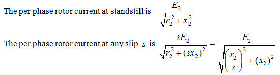 |
(13e) (13f) |
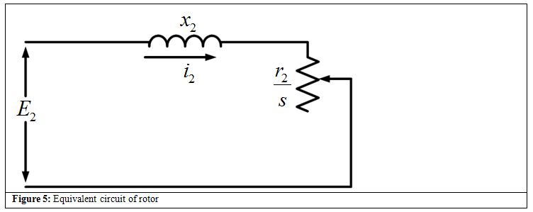
Based on equation 13f the equivalent circuit of the rotor is shown in Figure 5 .