Induction Motor for EV and HEV Application
The topics covered in this chapter are as follows:
- Traction Motors
- Principle of Operation of Induction Motor (Mathematical Treatment)
- Principle of Operation of Induction Motor (Graphical Treatment)
- Fluxes and MMF in Induction Motor
- Rotor Action
- Rotor e.m.f and Equivalent Circuit
- Complete Equivalent Circuit
- Simplification of Equivalent Circuit
- Analysis of Equivalent Circuit
- Thevenin's Equivalent Circuit
Principles of Operation of Induction Motor (Mathematical Treatment)
In Figure 1 a cross section of the stator of a three phase, two pole induction motor is shown. The stator consists of three blocks of iron spaced at 120° apart. The three coils are connected in Y and energized from a three phase system. When the stator windings are energized from a three phase system, the currents in the coils reach their maximum values at different instants. Since the three currents are displaced from each other by 120° electrical, their respective flux contributions will also be displaced by 120° electrical. Let a balanced three phase current be applied to the stator with the phase sequence A-B-C
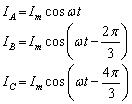 |
(1) |
The instantaneous flux produced by the stator will hence be
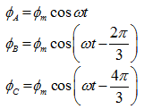 |
(2) |
The resultant flux at an angle θ from the axis of phase A is
(3) |
Substituting equation 2 into equation 3 gives
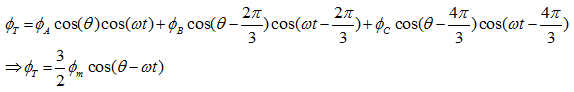 |
(4) |