Fluxes and MMF in Induction Motor
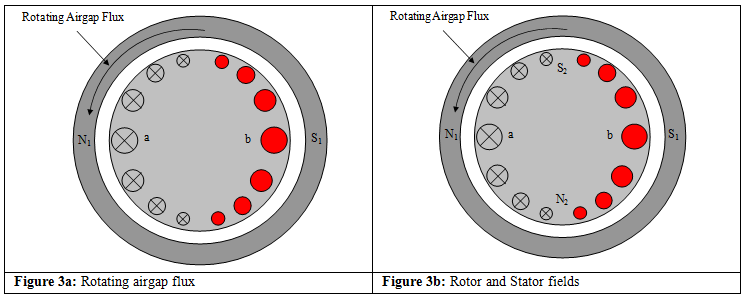
Although the flux generated by each coil is only alternating flux, the combined flux contributions of the three coils, carrying current at appropriate sequential phase angles, produces a two pole rotating flux. The rotating flux produced by three phase currents in the stationary coils, may be linked to the rotating field produced by a magnet sweeping around the rotor ( Figure 3a ). The rotating field cuts the rotor bars in its anti clockwise sweep around the rotor. According to Lenz's law, the voltage, current and flux generated by the relative motion between a conductor and a magnetic field will be in a direction to oppose the relative motion. From Figure 3a it can be seen that the bars a and b are just under the pole centers and have maximum electromotive force (e.m.f) generated in them and this is indicated by large cross and dots. The bars away from the pole centers have reduced magnitude of generated e.m.fs and these are indicated by varying sizes of dots and crosses. If the rotor circuit is assumed purely resistive, then current in any bar is in phase with the e.m.f generated in that bar ( Figure 3a ). The existence of currents in the rotor circuit gives rise to rotor mmf F2, which lags behind airgap flux Φm by a space angle of 90°. The rotor mmf causes the appearance two poles N2 and S2. The relative speed between the poles N1 , S1 and the rotor poles N2 , S2 is zero. Rotating pole N1 repels N2 but attracts S2. Consequently the electromagnetic torque developed by the interaction of the airgap flux Φm and the rotor mmf F2 is in the same direction as that of the rotating magnetic field ( Figure 3b ). The space phase angle between F2 and Φm is called the load angle and for this case it is 90° ( Figure 3b ). The torque produce is given by
(5) |