Induction Machine (IM)
Like synchronous machine, the stator winding of an induction machine is excited with alternating currents. In contrast to a synchronous machine in which a field winding on the rotor is excited with dc current, alternating currents flow in the rotor windings of an induction machine. In IM, alternating currents are applied to the stator windings and the rotor currents are produced by induction. The details of the working of the IMs are given in the following lectures.
After having discussed the general features of the electrical machines, the question that arises is : how to analyse the machines? The analysis of electrical machines becomes simple by use of electrical equivalent circuits. The electrical equivalent circuits for the machines are discussed in the next section. One last concept that is relevant to electrical machines is principle of electrical and mechanical angle which is explained in the next section.
Electrical and Mechanical Angle
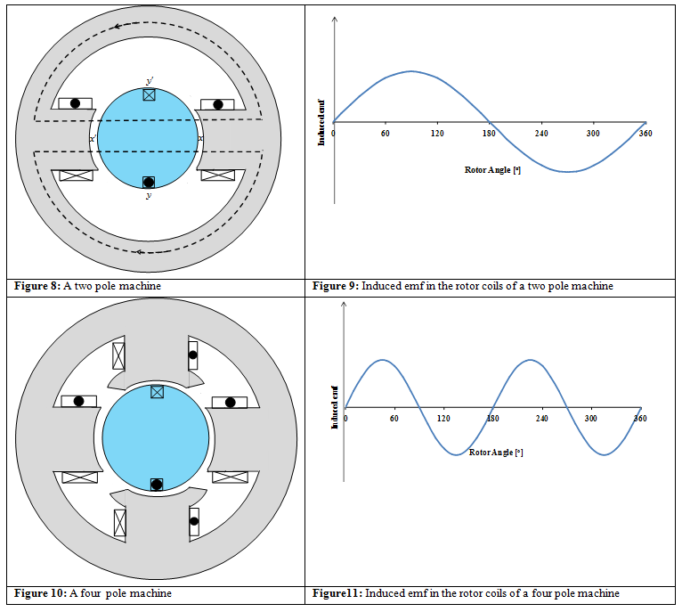
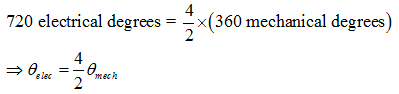
In Figure 8, it is assumed that the field winding is excited by a dc source and a coil rotates in the air gap at a uniform angular speed. When the conductor is aligned along y - y' axis, the e.m.f induced is zero. Along x - x' axis the induced e.m.f is maximum. In one revolution of the coil, the e.m.f induced is shown in Figure 9. If the same coil rotates in a 4 pole machine (Figure 10), excited by a dc source, the variation in the magnetic flux density and the induced e.m.f is shown in Figure 11. From Figure 11 it can be seen that in one revolution of 360 mechanical degrees, 2 cycles of e.m.f (720 electrical degrees) are induced. The 720 electrical degrees in a 4 pole machine can be related to 360 mechanical degrees as follows
 |
(5) |