Voltage Control of Three Phase DC-AC Inverter using Sinusoidal PWM
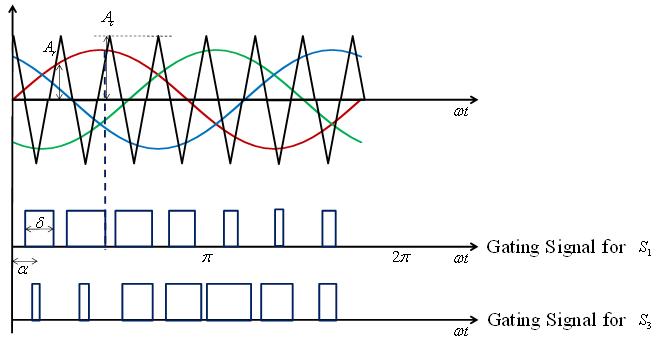
The generation of gating signals for a three phase DC-AC inverter with sine PWM are shown in Figure 8 . There are three sinusoidal reference waves (vra , vrb , vrc) each shifted by 120° . A triangular carrier wave is compared with the reference signals to produce the gating signals. Comparing the carrier signal vcr with the reference phases vra , vrb , vrc produces the signals for gates 1, 2 and 3 (g1, g2, g3). The instantaneous line-to-line output voltage is
![]() (17)
(17)
The output voltage is generated by eliminating the condition that two switching devices in the same arm cannot conduct at the same time.
|
Figure 8: Voltage and Current waveforms for three phase Sinusoidal PWM |
Suggested Reading:
[1] M. H. Rashid, Power Electronics: Circuits, Devices and Applications , 3 rd edition, Pearson, 2004
[2] V. R. Moorthi, Power Electronics: Devices, Circuits and Industrial Applications , Oxford University Press, 2007