Voltage Control of Single Phase Inverter
The single phase DC-AC inverter considered in this section is shown in Figure 2.
Single Pulse Width Modulation
In this modulation only one pulse per half cycle exists and the width of the pulse is varied to control the inverter output voltage. The generation of the gating signals and the output voltage of single phase full-bridge inverters are shown in Figure 3 . The gating signals are generated by comparing a rectangular reference signal of amplitude Ar with a triangular carrier wave of amplitude Ac. The frequency of the reference signal determines the fundamental frequency of the output voltage . The ratio of Ar to Ac is the control variable and defined as the amplitude modulation index or modulation index and is given by
![]() (1)
(1)
The output voltage shown in Figure 3 can be expressed as
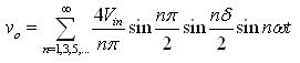 (2)
(2)
And the rms value of the output voltage is
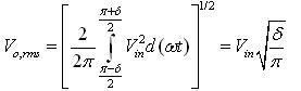 (3)
(3)
The relation between δ and modulation index M is:
 (4)
(4)
Using equation 4 , the rms voltage can be expressed as
![]() (5)
(5)
The load current in case of resistive load is
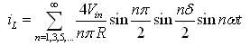 (6)
(6)
For R-L load, the load current is given by
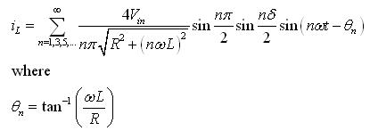 (7)
(7)