Module 2 : Modeling Discrete Time Systems by Pulse Transfer Function

Lecture 5 : Sampled Signal Flow Graph

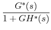
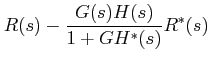
The transfer function between the inputs and continuous data outputs are obtained from composite SFG using Mason's gain formula.

In the composite SFG, the output nodes of the sampler on the sampled SFG are connected to the same nodes on equivalent SFG with unity gain. If we apply Mason's gain formula to the composite SFG:

$\displaystyle \frac {C^{*}(s)}{R^{*}(s)}$
$\displaystyle =$ $\displaystyle \frac {G^{*}(s)}{1+GH^{*}(s)}$  
$\displaystyle E(s)$
$\displaystyle =$ $\displaystyle R(s)-\frac {G(s)H(s)}{1+GH^{*}(s)}R^{*}(s)$  

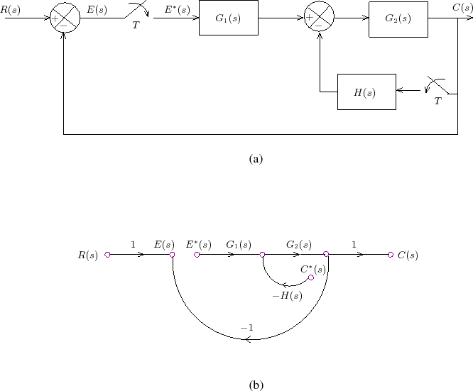
Example 2: Consider the block diagram as shown in Figure 3(a).

Figure 3: (a) Block diagram and (b) sampled signal flow graph for Example 2
\begin{figure}\centering
\input{m2l5f3.pstex_t}\end{figure}