4. Binding using Left-Edge Algorithm
In left edge algorithm, we first short, in ascending order, the variables (or operations) according to the starting step of their life times. If there are more than one variable at the same level in the order (because of the same starting control step), then those variables are ordered based on the last control step. For example, if there are three variables a,b,c where, a has life time from step1 to step3, b has life time from step1 to step2 and c has life time from step2 to step3, then the order is a<b<c . If there are some variables with same start and end control step then they are ordered arbitrarily. Figure 8 illustrates lifetime of the variables for the schedule shown in Figure 1, arranged according to the order discussed above.
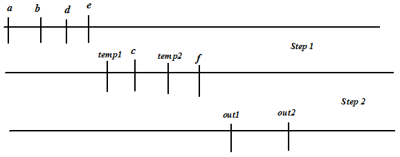
Figure 8. Lifetime of the variables for the schedule shown in Figure 1, arranged in ascending order
Once the variables are arranged, we start with a register and traverse the variables (arranged in order) from left to right. While traversing, we start filling the register with variables such that there is no overlap in the register. Once the traversal is complete, we delete the variables from the arranged list that are filled in the register. If there are variables remaining in the list we take another register and repeat the procedure.
Figure 9 illustrates list scheduling for the variables (ordered) shown in Figure 8. We take register R1, and in the process of traversal we first start with variable a ; variable a is filled in R1 and it occupies step1 in R1. Following that we traverse variables b,c,d but cannot put them in R1 as they would overlap with a . Variable temp1 can be filled in R1 and it occupies step2. Finally variable out1 is put is R1. As there are more variables, we take another register R2 and repeat the procedure. Final binding, comprising 4 registers is shown in Figure 9. The circuit corresponding to this binding is shown in Figure 10 (we assume that operations 01,02 are binded to adder1 and operations 03,04 are binded to adder2). It may be noted that three multiplexers are required in this case, while the binding corresponding to Figure 2 requires two multiplexers.
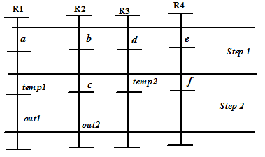
Figure 9. List scheduling
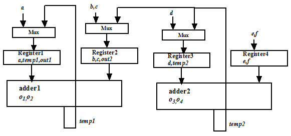
Figure 10. Circuit for the binding shown in Figure 9.