3. Binding using clique partitioning
In clique partitioning based binding, the operations and variables are modeled in terms of a graph. Each variable (if storage binding is done, or operation, if functional unit binding is done) is modeled by a node in the graph. There is an edge between two nodes only if the lifetime of the variables (or operations) does not overlap. Figure 4 illustrates lifetime of the variables for the schedule shown in Figure 1. It may be noted that variables a,b,c,d are required in step1 only, thereby making their life time only step1. Similarly, life time of variables temp1,c,temp2,f is step2 and out1,out2 are alive only in step3. The graph representation of the variables, in terms of lifetime is illustrated in Figure 6.
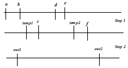
Figure 5. Lifetime of the variables for the schedule shown in Figure 1
By looking at Figure 6, it may be noted that there if two variables exits whose lifetime do not overlap, then they are connected by an edge. For example, out1 and a are connected by an edge while a and b are not.
Now, for binding, we need to determine maximal cliques in the graph. The clique problem is to find complete subgraphs ("cliques") in a graph, i.e., sets of elements where each pair of nodes is connected. In other words, a clique in an undirected graph is a subset of its vertices such that every two vertices in the subset are connected by an edge. A maximal clique is a clique that cannot be extended by including one more adjacent node, that is, a clique which does not exist exclusively within another larger clique.
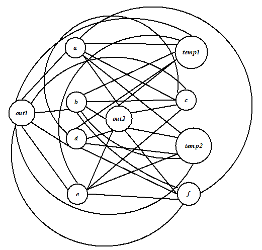
Figure 6. Graph representation of the variables in terms of lifetime shown in Figure 5
For each maximal clique we need a hardware resource of the corresponding type. All variables (or operations) corresponding to the nodes of the maximal clique are binded to the hardware module selected for the clique. Now we discuss how, the above-mentioned procedure produces an optimal binding. It may be noted that a maximal clique comprises maximum possible nodes where each of them has an interconnecting edge. As discussed before, an edge exists between nodes whose corresponding variable (or operation) do not have overlapping life-time. So variables (or operations) in a clique can share a resource. If we have maximal cliques then we can have minimal number of modules as more variables (or operations) share a single hardware module.
The maximal cliques for the graph of Figure 6 are shown in Figure 7.