As in the case of gate level digital circuits, testing the physical defects of memory is not possible. The other possible testing mechanism is to see if each cell can be written with the desired value (0/1) and be read back, which necessitates modeling of physical defects as logical faults. In case of memory, if logical fault model is to be applied then first a logic functional model is to be developed. Modeling faults as logical faults in a logical functional model makes the testing approach independent of the technology and the manufacturing process. Figure 1 shows logic functional model of a memory.
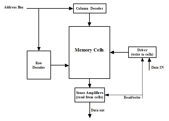
Figure 1. Logic functional model of memory
from the data bus. Also there is a read/write select line in the memory. This is a very broad level view of how memory works and detailed information can be found in [3]. For testing of memory this top level idea of its working suffices. It may be noted that from the testing perspective we would only check if
• Required value (0/1) can be written to a cell
• The stored value can be read from a cell
• The proper cell is accessed, i.e., the row and column decoder do not have faults.
It may be noted that the row and column decoders are digital circuits implemented using logic gates (which are different from memory cell implementation). The sense amplifier and driver are analog circuits. In testing of memory, we do not consider the decoders as gate level digital circuits nor the sense amplifier and driver as analog circuits. For the decoders, we test the functionality whether they can access the desired cells based on the address in the address bus. For the amplifier and driver we check if they can pass the values to and from the cells correctly.
There can be a large number of logical faults based on the memory model of Figure 1. However, the following faults called “reduced functional faults” are sufficient for functional memory testing [4,5].
• Stuck-at fault
• Transition fault
• Coupling fault
• Neighborhood pattern sensitive fault
• Address decoder faults