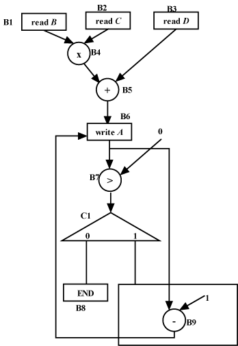
Figure 2. CDFG for the Verilog HDL in Figure 1
The CDFG for Verilog HDL (Figure 1) is shown in Figure 2. In Figure 1 it may be noted that there are three input variables (B,C and D) which must be read from input lines to registers. So corresponding to reading of each variable in registers we have storage node; B1,B2 and B3 are storage nodes (Figure 2). In the Verilog code there is a one time computation “initial begin A: = B * C + D; end”. For this computation we see that there are 2 sub-computations, namely “*” and “+”. So we have two operational nodes, B4 and B5 for “*” and “+”, respectively. The edge ![]() corresponds to transfer of value of B, which gets changed (i.e., new value read) due to processing (reading) in B1. The edge
corresponds to transfer of value of B, which gets changed (i.e., new value read) due to processing (reading) in B1. The edge ![]() corresponds to transfer of values (B and C to “B*C”), which get changed due to processing (“*”) in B4. After the computation “initial begin A: = B * C + D; end”, the value is stored in A; this is captured by storage node B6. B7 is the operational node that checks 0 with A; output is 0 if A<0 and 1, otherwise. The output of B7 (carried by edge
corresponds to transfer of values (B and C to “B*C”), which get changed due to processing (“*”) in B4. After the computation “initial begin A: = B * C + D; end”, the value is stored in A; this is captured by storage node B6. B7 is the operational node that checks 0 with A; output is 0 if A<0 and 1, otherwise. The output of B7 (carried by edge ![]() controls the control node C1.
controls the control node C1. ![]() is the control flow edge, which corresponds to the condition (A>0) required for execution/exit of the while loop. Node C1 is a control node responsible for deciding data flow direction after the condition “A>0” is checked at B7. If value transferred by
is the control flow edge, which corresponds to the condition (A>0) required for execution/exit of the while loop. Node C1 is a control node responsible for deciding data flow direction after the condition “A>0” is checked at B7. If value transferred by ![]() is 0 then the loops exits at B8, else computation “A=A-1” is done at B9 and the loop continues.
is 0 then the loops exits at B8, else computation “A=A-1” is done at B9 and the loop continues.
Now we discuss in brief, CDFGs for some other frequently used constructs of HDLs. Figure 3 illustrates CDFG for “case” statement in Verilog. This is similar to if-then statement; however, we have an edge for all the cases of the case statement in the control node.
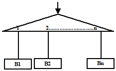
Figure 3. CDFG for “case” statement in Verilog
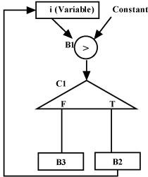
Figure 4. CDFG for “for loop” in Verilog