1. Introduction
As discussed in the last lecture, almost all steps of VLSI design are automated. Any automated procedure requires that input data being provided is in some predefined format. Also, the models used to represent the inputs and transformations (changes of the input) should be efficient for execution of the procedure. For example, in case of High Level Synthesis (HLS) the input specifications are generally in some Hardware Definition Language (HDSs) like Verilog [1], VHDL [2], System C [3] etc. The HDL specifications are represented using several modeling paradigms like Control and Data Flow Diagram (CDFG) [4], DeJong's hybrid flow graph [5], SSIM flow graph [6], Finite state machine with data [7] etc., which are suitable for scheduling, allocation and binding procedures. Sometimes timing constrains (on execution of steps) are also given in the specifications, which are modeled by the above paradigms, however, with timing parameter included e.g., CDFG with timing, DF with timing and CF with timing.
In this lecture, we will discuss CDFG paradigm for modeling of high-level hardware descriptions (given in Verilog). CDFG is one of the most widely used modeling paradigm and the others mentioned above are not much different; for details of other paradigms the reader may look into the respective references.
2. Control and Data Flow Diagram (CDFG)
A CDFG is a directed graph ![]() , where
, where ![]() is the set of nodes and
is the set of nodes and ![]() the set of directed edges
the set of directed edges ![]() .
.
In general, the nodes in a CDFG can be classified into one of the following types:
• Operational nodes: These are responsible for arithmetic, logical or relational operations (or computations); e.g., addition, equality checking etc.
• Control nodes: These nodes are responsible for control operations like conditions, loop constructs etc.; e.g., case statements, while loop etc.
• Storage nodes: These nodes represent assignment operations associated with variables and signals; e.g., reading an input value to register etc.
The edges in a CDFG represent:
• Transfer of values (in variables that are changed due to processing in operational and storage nodes). A node needs data generated by its predecessor nodes and generates new data needed by its successors. Nodes operate on the data of the incoming edges. The resulting data is put on the outgoing edges.
• Control flow from one node to another. An edge can also represent a condition, e.g., while implementing loop constructs, if/case statements etc.
Now we illustrate different types of nodes and edges using a simple example. Let us take the simple Verilog HDL code given in Figure 1.
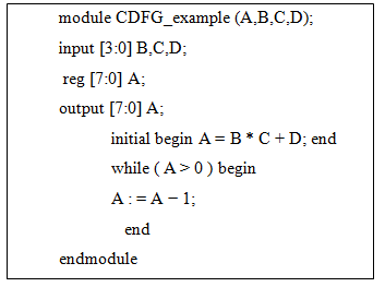
Figure 1. Verilog code