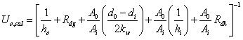
Overall heat transfer co-efficient (Uo,cal ):
Fouling factor, Rdk =0.001 h ft2 °F Btu -1 for kerosene and Rdg = 0.0005 h ft 2 °F Btu -1 for gasoline is taken for this service.
 (1.6)
(1.6)
Let select, Admirality brass as tube material with thermal conductivity, kw =70 Btu h -1 ft-1 °F-1 .
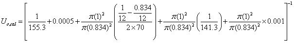
Uo,cal = 53.5 Btu h -1 ft -2 °F-1
Now, 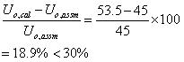
Therefore, the calculated overall heat transfer co-efficient is well within the design criteria.
VI. Pressure drop calculation
VI.1. Tube side pressure drop:
Friction factor f = 0.00028 x 144 for Re = 0.04032 ft2 /ft2 for Re=11571.4 ( [3] page 836 ]
at = (no. of tubes)×(flow area per tube)/(no. of passes)
![]()
= 0.232 ft 2
Tube side mass velocity: ![]()
=646552 lb. h-1.ft-2
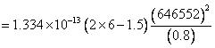
Frictional pressure drop: 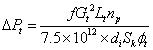
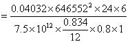
= 5.81 psi
Return loss ΔPrt : (due to change in flow direction of the tube side fluid)
![]()
= 0.73 psi
Total tube side drop neglecting nozzle loss:
![]() (1.8)
(1.8)
=5.81+0.73
=6.54 psi<10 psi
Therefore the tube side pressure drop is within the maximum allowable pressure drop of 10 psi.
VI.2. Shell side pressure drop calculation
Tube clearance, C =0.25″
Spacing, B =15.5″
as = 0.444 ft2
Mass velocity, GS = 210526 lb. h-1.ft-2
Re = 35668
No of baffles, ![]()
Friction factor, f = 0.0017 X 144= 0.2448 ft2 / ft2 with 25% cut segmental baffles ( [3] page 839 )
Shell side frictional pressure drop ΔPs :
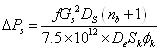
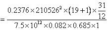
=1.4 psi <7 psi
ΔPrs = 0 (in case of single shell pass flow)
Total shell side drop neglecting nozzle loss:
![]() =
1.4 psi (1.9)
=
1.4 psi (1.9)
Therefore the shell side pressure drop is within the maximum allowable pressure drop of 7 psi.
VII. Over surface and over design
Over surface = ![]()
The clean overall heat fransfer co-efficient: ![]()
![]() =
141.3×0.834=117.8
Btu h-1 ft-2 °F-1
=
141.3×0.834=117.8
Btu h-1 ft-2 °F-1
Uc = 66.98 Btu hr -1 ft-2 °F-1
% Over surface = ![]()
=20% (acceptable)
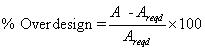
Over design:
The design area of heat transfer in the exchanger, ( nt =318) :
![]() =π×
=π× ![]() ×24×368=2312 ft2
×24×368=2312 ft2
The required heat transfer area (where, nt =335):
![]() = π×
= π× ![]() ×24×335=2105 ft2
×24×335=2105 ft2
% Overdesign=9.8% which is within the acceptable limit.
Refer module # 2 for the mechanical design of shell and tube heat exchanger .