- Place the scanner into the center of the microscope head’s base plate ensuring that it fits in the slot perfectly (Figure 36.6G).
- Fix the scanner into position by tightening the locking screws (Figure 36.6H).
- Plug the scanner’s connectors on the microscope head.
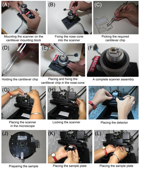
Figure 36.6 Steps showing fixing the different components of the AFM. The steps are discussed in the text
- Switch ON the laser.
- Place a small piece of white paper under the scanner.
- Use the laser tilting screws and the detector alignment screws to obtain a clear red spot on the paper.
- Move the laser spot in the direction perpendicular to the cantilever until diffraction of the laser beam is seen on the paper and the Lucite block (Figure 36.7A). Lucite block acts as a screen for viewing safety; the laser beam reflected from the cantilever is projected on the Lucite block. The diffraction of laser beam is suggestive of the beam hitting one of the cantilever legs (Figure 36.7A).
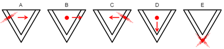
Figure 36.7 Steps showing focusing of the laser on the cantilever just opposite to the probe.