Exercise Problems
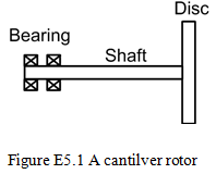
Exercise 5.1 Obtain the forward and backward synchronous transverse critical speeds for a general motion of a rotor as shown in Figure E5.1. The rotor is assumed to be fixed supported at one end. Take mass of the thin disc m is 5 kg and its radius is 15 cm. The shaft is assumed to be massless and its length and diameter are 0.2 m and 0.02 m, respectively. Take shaft Young’s modulus E = 2.1 X 10¹¹ N/m2. Obtain first two forward and backward synchronous transverse critical speeds by drawing the Campbell diagram also.
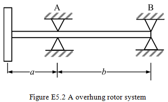
Exercise 5.2 Consider a rotor system as shown in Figure E5.2. The mass of the thin disc m, is 5 kg and the diametral mass moment of inertia, Id, is 0.02 kg-m2. The shaft lengths are a = 0.3 m and b = 0.7 m. The diameter of the shaft is 10 mm. Obtain first two forward and backward synchronous transverse critical speeds by drawing the Campbell diagram. [Hint: Obtain the influence coefficicnts at disc location and the analysis given in Section 5.4 can be applied for this case also].
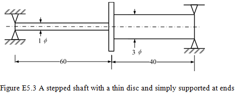
Exercise 5.3 Coniser a rotor system as shown in Figure E5.3 (In the figure all dimensions are in cm). Consider the shaft as massless and is made of steel with the Young’s modulus, E = 2.1 (10)11 N/m2. The thin disc has the mass of 10 kg and a radius of 15 cm. The shaft is simply supported at ends. Obtain first two forward and backward synchronous transverse critical speeds by drawing the Campbell diagram. [Hint: Obtain the influence coefficients at disc location and the analysis given in Section 5.4 can be applied for this case also].
Exercise 5.4 Formulate the standard eigen value problem for following equations of motion
![]()
where [M], [C], [G] and [K] are the mass, damping, gyroscopic and stiffness matrices respectively, {x} and {f} are the response and force vectors respectively, and ω is the spin speed of the rotor. Discuss characteristics of eigen values and interpret them physically for the present case.
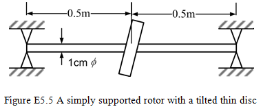
Exercise 5.5 Find transverse critical speeds of a rotor system shown in Figure E5.5. The shaft is massless and Young’s modulus E = 2.1 X 10¹¹ N/m2. The thin disc properties about its principal axis are Ip = 0.02 kg-m2 and Id = 0.01 kg-m2 and the tilt of disc from vertical axis is φ = 20. Discuss whether gyroscopic effects will be present or not? Obtain critical speeds accordingly. [Hint: Since the disc is located at the centre of the shaft span, hence there would not be any precession of the spinning disc. If it has an unbalance then, the tilting of the disc will contribute to the unbalance moment (M = (Ip - Id)ω2φ) due to presence of radial and axial eccentricity. Hence, gyroscopic effects would not be present for the present case].
Exercise 5.6 A shaft of modulus of rigidity, EI, of total length, l, is supported “freely” at its ends. At a quarter length between the end bearings the shaft carries a disc of mass, m, and of diameter moment of inertia, Id. Find (a) the non-rotational natural frequency, (b) the transverse whirl natural frequency. For the circular cylinder following relations for the polar moment of inertia, Ip, and diametral moment of inertias, Id, are given ![]() where m is the mass of the cylinder, r is the radius of the cylinder and l is the length of the cylinder.
where m is the mass of the cylinder, r is the radius of the cylinder and l is the length of the cylinder.
Exercise 5.7 A shaft of total length, l, on end bearings carries two discs at the quarter-length points. The discs have mass, m, and inertia, Id, and the shaft modulus of rigidity is EI. (a) derive equations for the whirling shaft, where the whirling frequency is equal to spin speed, (b) make the frequency equation dimensionless in terms of the critical speed function ![]() and the disc effect
and the disc effect ![]() (c) find the whirling speed for the following three cases: (i) μ = 0, (ii) μ → ∞ , and (iii) D = 1/12.
(c) find the whirling speed for the following three cases: (i) μ = 0, (ii) μ → ∞ , and (iii) D = 1/12.
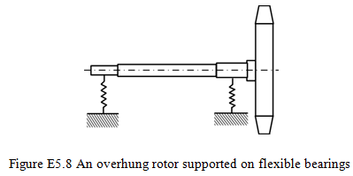
Exercise 5.8 Obtain the forward and backward transverse critical speeds of the rotor system shown in Figure E5.8. Take the shaft as rigid. It is assumed that it oscillates (processes) about its center of gravity while whirling (i.e., pure tilting without linear motion). The effective torsional stiffness of the bearings is N-m/mm, the polar and diametral mass moment of inertia of the rotor is 0.3 kg-m2 and 0.2 kg-m2, respectively. Consider the gyroscopic effects. [Answer:ωFnf = 20192.57 rad/s]
Exercise 5.9 A massless shaft of total length, l, between bearings (simply supports) carries at its center a disc of diameteral mass moment of inertia Id. The disc is keyed on at a small angle φ0. When rotating at constant angular speed ω, the centrifugal forces tend to diminish the angle φ0 to a new value (φ0 - φ). Find the ratio φ/φ0 as a function of the speed ω.
Exercise 5.10 Consider a Jeffcott rotor, a simply supported shaft with a central disc. Consider only the titling mode of vibration with no linear displacement. (i) find the natural frequency of this motion for non-rotating disc. (ii) find the natural frequency (or frequencies) ωnf for the case of a disc rotating with angular speed, ω. Plot the variation of the obtained natural frequency with respect to the angular speed of the rotor. [Hint: The moment required at the disc to produce a unit angular displacement (tilting) at that location is given as k = 12EI/l. While plotting, it is always convenient to non-dimensionalise the parameters, hence, the natural frequency and angular speed for part (ii) can be non-dimesionalised by the frequency obtained in part (i)].
Exercise 5.11 Obtain the transverse critical speed for the synchronous motion of a rotor as shown in Figure 1 by considering the gyroscopic moment effects. The shaft is assumed to be simply supported at both ends, and disc has the diameter of D and the thickness of t. It is assumed that even when the thickness of the disc is large, the disc is attached to the shaft at mid span without interfering the motion of the shaft. Consider dimensions of the disc for the following four cases (i) D = 0.2 m, t = 0.0082 m; (ii) D = 0.0721m, t = 0.0628 m; (iii) D = 0.0689 m, t = 0.0689 m; and (iv) D = 0.0547 m, t = 0.1093 m. The shaft is assumed to be massless and its length and diameter are 1 m and 0.01 m, respectively; with a = 0.75 m. Take the Young’s modulus of the shaft material as 2.1 X 10¹¹ N/m2 and the density of the material as 7800 kg/m3.
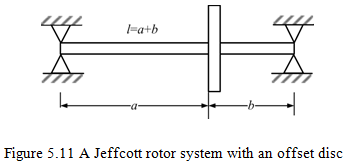
For the simply supported shaft influence coefficients are defined as:
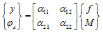
with
![]()