5.6 Gyroscopic Effects by the Dynamics Approach
In the present section gyroscopic effects of a disc on the dynamics of a rotor will be studies. Fig. 5.39(a) shows a Jeffcott rotor with an offset disc. First the governing differential equations of motion of the disc from free body diagrams to be obtained. Free body diagrams of the disc in two orthogonal planes are shown in Figures 5.39(b) and (c). In the z-x plane the linear and angular (tilting) displacements are x and φy, respectively. Both the linear and angular (tilting) displacements of the disc are chosen in the positive axis direction. Similarly, in the y-z plane the linear and angular (tilting) displacements are y and φx, respectively.
Free body diagrams also show the angular momentum Ipω and the change in the angular momentum Δ(Ipω). For example in the z-x plane the change in the angular momentum is in the positive x-direction, which gives rise to a clockwise gyroscopic moment, ![]() , on to the disc in y-z plane as shown in Figure 5.39(c). In the y-z plane the x-axis is into the plane of paper (it is shown by a symbol
, on to the disc in y-z plane as shown in Figure 5.39(c). In the y-z plane the x-axis is into the plane of paper (it is shown by a symbol ![]() which represents the tail of the arrow). Similarly, in y-z plane the change in the angular momentum is in the negative y-direction, which gives rise to clockwise gyroscopic moment,
which represents the tail of the arrow). Similarly, in y-z plane the change in the angular momentum is in the negative y-direction, which gives rise to clockwise gyroscopic moment, ![]() , on to the disc in z-x plane as shown in Figure 5.39(b). In the z-x plane the y-axis is out of the plane of paper (it is shown by a symbol
, on to the disc in z-x plane as shown in Figure 5.39(b). In the z-x plane the y-axis is out of the plane of paper (it is shown by a symbol ![]() , which represents the head or the tip of the arrow). Rotary inertias are also shown in both planes, the direction of which is opposite to the angular displacement. Since the rotary inertia moments are due to inertia these are shown by dotted arcs.
, which represents the head or the tip of the arrow). Rotary inertias are also shown in both planes, the direction of which is opposite to the angular displacement. Since the rotary inertia moments are due to inertia these are shown by dotted arcs.
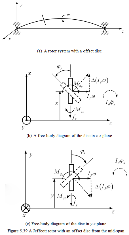
Let ƒy and ƒx be restoring forces and Mzx and Myz be restoring moments (signs of which are opposite to the respective linear and angular displacements). These resulting forces and moments are due to the shaft elasticity. From Figure 5.39, equations of motion can be written as
(5.82) |
and
(5.83) |
The direction of change in the angular momentum gives the direction of moment to be applied to the disc by the shaft to produce precision such that angular momentum tries to get align in the direction of the precession of the disc. The shaft gets opposite direction reaction moment. Gyroscopic moments are expressed as
![]()
Hence, equations of motion can be written as
(5.84) |
and
(5.85) |
For a symmetric shaft the coupling of motions due to elastic force in the vertical and horizontal planes will not be there, hence from the elementary strength of materials, we have
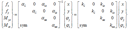 |
(5.86) |
where subscripts: l and a represent the linear and the angular, respectively. On substituting equation (5.86) into equations (5.84) and (5.85), we get
(5.87) |
and
(5.88) |
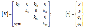
Above equations could be combined in the standard matrix form as
(5.89) |
with
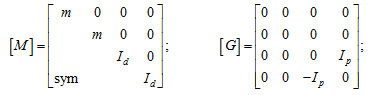 |
(5.90) |
and
 |
(5.91) |
where [M] is the mass matrix, [K] is the stiffness matrix, and [G] is the gyroscopic matrix which is a skew-symmetric matrix. Let the general solution be
(5.92) |
so that
(5.93) |
where v is the asynchronous whirl frequency. Hence, equation gives
(5.94) |
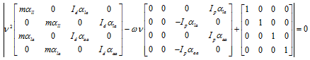
By the direct approach, since above equation is a homogeneous equation and for the non-trivial solution, the determinant should be zero. Hence, we get
![]()
or
![]()
On substituting matrices, we get
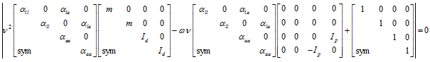
This can be simplified as