Example 13.2 In a dynamic balancing of a rigid rotor by a cradle balancing machine the following measurement were obtained when fulcrumed at F1 (i) for a known trial mass at a fixed radius when kept at different angular position at regular interval of 300 the following vibration amplitudes (all in mm) were obtained: 3, 5, 8, 6, 5, 3, 2, 4, 7, 8, 6, 5. 4 (ii) when at a constant angular position and at fixed radius corresponding to the minimum vibration amplitude different masses were tried the following vibration measurements were obtained (gm, mm): (1, 1.2), (1.2, 1.4), (1.4, 1.6), (1.6, 1.4), (1.8, 0.9), (2.0, 0.8), (2.2, 1.2), (2.4, 1.5), (2.6, 1.8). Obtain the unbalance mass and its location in the plane 2.
Solution: From the first set of measurement the location of the angular position is 1800 corresponding to 2 mm displacement. From the second set of measurements the magnitude of the unbalance mass is 2.0 gm corresponding to the minimum vibration amplidue of 0.8 mm.
Answer
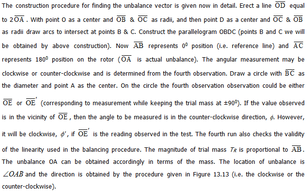
A systematic balancing method: This method is aimed to reduce the number of measurements while using the cradle balancing machine. This method also requires measurements in the cradle balancing machine and correction masses at plane I and II are obtained by fulcruming at F2 and F1, respectively. A procedure to determine the correction mass and location at one plane at a time can be laid down as follows, based on only four observations of amplitude : (i) without any addition of the trial mass to the rotor (ii) with a trial mass at θ = 00, where θ is measured from a conveniently chosen location on the balancing plane (iii) with the same trial mass at 1800 and (iv) with the same trial mass at θ = ±900. All measurements have to be performed at the same speed.
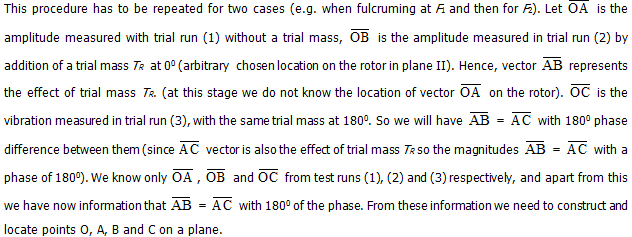
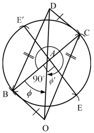
Figure 13.12 A construction procedure for finding the residual unbalance vector