13.3 Balancing of Practical Rigid Rotor
In the present section now practical methods of the rigid rotor balancing will be described. In practical rotors axial and radial locations residual unbalances and its orientations are unknown. In soft support machines, the resonant frequency of the rotor support system is low and the rotor runs at a speed above the resonance of the support system. Vibratory amplitudes are measured, which are then converetd to forces. In hard support system, the support natural frequency is very high and they measure the rotor unbalance forces directly, independent of rotor mass and configuration. Depending upon the geometry of rigid rotors, a single plane or two plane balancing methods are employed. In the present section, both the single plane balancing and the two plane balancing will be described in detail.
13.3.1 Single plane balancing: In the actual practice location (radial as well as angular)) of centre of gravity point G is unknown in the single plane rotors. The orientation of point G can be obtained by keeping the rotor on frictionless (knife edge) supports and gently allow it to rotate freely without any external drive as such (may be a small toque by hand to initiate its rotation). The rotor becomes stationary after some time with heavy spot (G) vertically downwards. It can be repeated to confirm the orientation of the residual unbalance (or heavy spot) and it can be marked by chalk or any other means. Now we will place a correction mass at 1800 to the heavy spot (i.e., at the light spot) and again allow rotor to rotate freely by gentle push of the rotor. (i) If the marked heavy spot again comes vertically downwards that means the correction mass m to be increased. (ii) If the marked heavy spot comes vertically upward position, means correction mass is more, and it has to be decreased. (iii) If heavy spot rests at some other position, means rotor is nearly balanced. This can be confirmed by freely rotating the rotor again and finding whether it rests always at some indifferent equilibrium position. Such a process is called the static balancing of rotor (disc) and it is valid for a rotor with only one disc or balancing is required in the single plane only. For the single plane rotor, the static balancing rotor will also be dynamically balanced.
13.3.2 Two plane balancing (Cradle balancing machines): The rotor has to be removed from the installation and is placed on the bearings of a cradle balancing machine as shown in Figure 13.10. Two procedures will be described (i) Hit and trial method: It requires large number of measurements to obtain correction masses at two balancing planes (ii) A systematic method: It requires only eight measurements to obtain correction masses at two balancing planes.
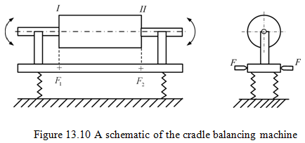
Hit-and-trial balancing method: The cradle is placed on four springs and can be fulcrum about F1 or F2 to form a simple vibrating system to oscillate about F2 or F1 , respectively. Two fulcrum can be located at two chosen balance planes (i.e. I and II), where the correction mass to be added. The rotor can be driven by a motor through a belt pulley arrangement. If the spring system is such that the natural frequency of the system is in the range of motor speed, the phase angle or the location of the mass in either plane can be determined as follows. The cradle can be hinged in plane I by fixing F1 and releasing F2. Run the rotor to resonance, observing the maximum amplitude to the right of fulcrum F2. This vibration is due to all the unbalance in plane II, since the unbalance in plane I has no moment about F1. Use a trial mass at a chosen location and determine the amplitude of vibration.
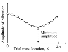
Figure 13.11(a) Variation of vibration amplitudes versus trial mass angular locations
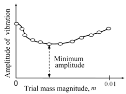
Figure 13.11(b) Variation of vibration amplitudes versus trial mass magnitudes
Make a plot of this amplitude for different location of the same trial mass (see Fig. 13.11a). The trial mass for correction is added at the location where the amplitude of vibration is minimum. Increase or decrease the trial mass at the same locations, until the desired level of balance is achived (see Fig. 13.11b). This will give correction mass for plane II. Similar procedure can be repeated by Fixing F2 and releasing F1 to get correction massk at plane I. This procedure is tedious and sometimes may be time consuming.