![]()
On substituting equation(10.45) into equation(10.43) , we get
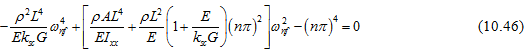
On solving equation(10.46)for![]() , we get
, we get
![]()
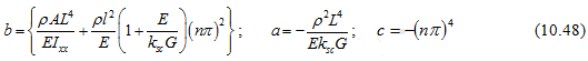
with
The above exact solution will be used for comparing natural frequencies for a simply supported end condition of a shaft with the finite element method as a benchmark solution for the convergence study. On the similar lines for other boundary conditions expressions of natural frequencies could be attempted.
10.3 Finite Element Formulations of the Timoshenko Beam
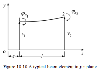
For the finite element analysis, we need to discretise the beam into number of elements as shown in Fig. 10.9. Consider a finite element of the shaft of length l in an elemental co-ordinate system x-y-z . Since the two orthogonal transverse plane motions are uncoupled, the deformation of the element is initially considered in the y-z plane with two nodes 1 and 2 as shown in Figure 10.10. The motion in z-x plane could be analysed in the similar lines. Let v be the nodal translational transverse displacement of the shaft element. Let ![]() be the total slope of the beam, which consists of two parts, one due to the bending, which is φx and other due to the shear, which is β and is given by
be the total slope of the beam, which consists of two parts, one due to the bending, which is φx and other due to the shear, which is β and is given by ![]() . From the displacement field of equation , we know that the axial displacement of a point P (x,y,z) at a distance y from the centre line is only due to the bending slope and that the shear force has no contribution to this. In previous section we observed that there are two independent variables in this problem (i.e ., v and φx).
. From the displacement field of equation , we know that the axial displacement of a point P (x,y,z) at a distance y from the centre line is only due to the bending slope and that the shear force has no contribution to this. In previous section we observed that there are two independent variables in this problem (i.e ., v and φx).

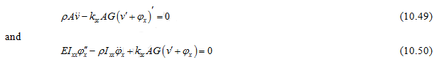
From equations(10.37)and(10.38)without considering the work done by the external forces, equations of motion are
In the finite element model, the continuous displacement field can be approximated in terms of descretised generalized-displacements of element nodes. In the present study, each element in single plane (e.g., y-z ) has two nodes and each node has two generalised displacements (one translational and the other rotational). Therefore, displacements could be obtained within the element by using appropriate shape functions to be derived in the subsequent subsection.