The situation now is that six classes of fuel cell have emerged as viable systems for the present and near future. Basic information about these systems is given in Table I. As well as facing up to different problems, the various fuel types also try to play to the strengths of fuel cells in different ways. The PEM fuel cell capitalizes on the essential simplicity of the fuel cell. The electrolyte is a solid polymer, in which protons are mobile. The chemistry is the same as the acid electrolyte fuel cell of Fig. 1. With a solid and immobile electrolyte, this type of cell is inherently simple; it is the type that shows by far the most promise for vehicles, and is the type used on all the most impressive demonstration fuel cell vehicles. This type of fuel cell is the main focus of this chapter. PEM fuel cells run at quite low temperatures, so the problem of slow reaction rates has to be addressed by using sophisticated catalysts and electrodes. Platinum is the catalyst, but developments in recent years mean that only minute amounts are used, and the cost of the platinum is a small part of the total price of a PEM fuel cell.
One theoretically very attractive solution to the hydrogen supply problem is to use methanol1 as a fuel instead. This can be done in the PEM fuel cell, and such cells are called direct methanol fuel cells. ‘Direct' because they use the methanol as the fuel as it is, in liquid form, as opposed to extracting the hydrogen from the methanol using one of the methods. Unfortunately these cells have very low power, and for the foreseeable future at least their use will be restricted to applications requiring slow and steady generation of electricity over long periods. A demonstration DMFC powered go-kart has been built, but really the only likely application of this type of cell in the near future is in the rapidly growing area of portable electronics equipment.
Although PEM fuel cells were used on the first manned spacecraft, the alkaline fuel cell was used on the Apollo and is used on the Shuttle Orbiter. The problem of slow reaction rate is overcome by using highly porous electrodes, with a platinum catalyst, and sometimes by operating at quite high pressures. Although some historically important alkaline fuel cells have operated at about 200°◦C, they more usually operate below 100◦°C. The alkaline fuel cell has been used by a few demonstration electric vehicles, always in hybrid systems with a battery. They can be made more cheaply than PEMFCs, but they are lower in power, and the electrolyte reacts with carbon dioxide in the air, which make terrestrial applications difficult.
Fuel cell electrodes
Fig. 2 is another representation of a fuel cell. Hydrogen is fed to one electrode, and oxygen, usually as air, to the other. A load is connected between the two electrodes, and current flows. However, in practice a fuel cell is far more complex than this. Normally the rate of reaction of both hydrogen and oxygen is very slow, which results in a low current, and so a low power. The three main ways of dealing with the slow reaction rates are: the use of suitable catalysts on the electrode, raising the temperature, and increasing the electrode area.
The first two can be applied to any chemical reaction. However, the third is special to fuel cells and is very important. If we take a reaction such as that of Eq. 3, we see that oxygen gas, and H+ ions from the electrolyte, and electrons from the circuit are needed, all three together. This ‘coming together' must take place on the surface of the electrode. Clearly, the larger the electrode area, the more scope there is for this to happen and the greater the current. This is very important. Indeed, electrode area is such a vital issue that the performance of a fuel cell design is often quoted in terms of the current per cm2.
The structure of the electrode is also important. It is made highly porous so that the real surface area is much greater than the normal length × width. As well as being of a large surface area, and highly porous, a fuel cell electrode must also be coated with a catalyst layer. In the case of the PEMFC this is platinum, which is highly expensive. The catalyst thus needs to be spread out as finely as possible. This is normally done by supporting very fine particles of the catalyst on carbon particles.
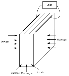
Fig. 2 Basic cathode-electrolyte-anode construction of a fuel cell.
The reactants need to be brought into contact with the catalyst, and a good electrical contact needs to be made with the electrode surface. Also, in the case of the cathode, the product water needs to be removed. These tasks are performed by the ‘gas diffusion layer’, a porous and highly conductive material such as carbon felt or carbon paper, which is layered on the electrode surface.
Fuel Cell Thermodynamics – Introduction
Fuel cell efficiency and efficiency limits
One of the attractions of fuel cells is that they are not heat engines. Their thermodynamics are different, and in particular their efficiency is potentially greater as they are not limited by the well-known Carnot limit that impinges on IC and other types of fuel burning engines. However, as we shall see, they do have their own limitations, and while fuel cells are often more efficient than IC engines, the difference is sometimes exaggerated.
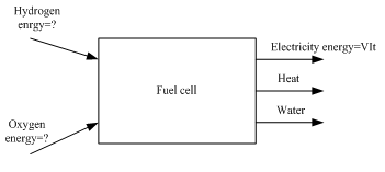
Fig. 3 Fuel cell inputs and outputs
At first we must acknowledge that the efficiency of a fuel cell is not straightforward to define. In some electrical power generating devices it is very clear what form of energy is being converted into electricity. With a fuel cell such energy considerations are much more difficult to visualize. The basic operation has already been explained, and the input and outputs are shown in Fig. 3. The electrical power and energy output are easily calculated from the well known formulas:
Power = VI and Energy = VIt |
(4) |