The Flux Weakening Controller
The schematic of the Flux Weakening Controller is shown in Figure 4. There are three inputs to the controller namely:
- The requested torque (Tereq)
- The measured speed (ωrn)
- The maximum possible stator current (Imn(max))
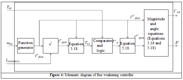
Based on these inputs, the steps involved in the operation of the controller are as follows:
- The three inputs are used to calculate the values of
 . In the Function 1 block the equation 11 is implemented. In this block the values of Ldn and Lqn have to be known in advance and can be obtained from measurements. The value of Vsn is set to the maximum value of voltage (in p.u.) that the power supply can deliver.
 - After the value of is determined, the value of
 is determined using
 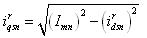 This is implemented in the Function 2 block.
 - Once the values of and are known, the maximum torque (Ten(max)) that the PM machine can produce is determined using equation 15b.
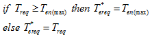
- In the comparator block the Ten(max) and Tereq are compared and the final torque value (T*ereq) that the machine has to produce is generated. The comparison is done using the following logic:
- Using the value of T*ereq the actual value of
 is calculated using equation 16. In equation 16, the value of
  used is same as that calculated in step i.
 - The magnitude of stator current I*mn and the load angle δ* are determined using equations 8 and 14.
- The values of I*mn and δ* go to the transformation block and the further operation of the control strategy is already explained in the previous section.
References:
[1] R. Krishnan, Electric motor drives : modeling, analysis, and control , Prentice Hall, 2001
Suggested Reading:
[1] P. C. Krause , O. Wasynczuk , S. D. Sudhoff , Analysis of electric machinery , IEEE Press, 1995