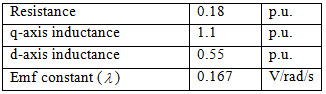
Table1: Parameters of the motor
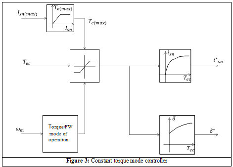
The details of the controller shown in Figure 3 are:
- The maximum stator current limit (Imn(max)) is given to the maximum torque block. In this block the Torque versus Current characteristic of the motor is implemented as lookup table or as a polynomial expression. The Torque versus Current characteristic of the PM machine parameters given in Table I is shown in Figure 4. The output of this block is the maximum possible torque (Ten(max)) that the motor can produce for the given value of Imn(max).
- The measured speed of the motor (ωrn) is required to determine whether the motor operates is clockwise or anticlockwise direction.
- In the comparator block the torques Ten(max) and Tereq are compared and output of this block is the minimum of the two values. This torque is referred to as T*ereq and it is equal to min(Tereq,Ten(max)).
- The value of T*ereq goes to the current block and angle block. In these blocks the equations 17 and 18 are implemented as polynomials or lookup tables. The output of these blocks are I*mn and δ*.
- The values of I*mn and δ* go to the transformation block and the further operation of the control strategy is already explained in the previous section.
Once the PM machine reaches the base speed, the flux weakening controller comes into action. The next section deals with the flux weakening controller.