In Figure 2 the variables of the form x*, x~ and ![]() denote command , measured and estimated values respectively. In case of parameters that are estimated , a subscript ” est ” is used. The working of the controller is as follows:
denote command , measured and estimated values respectively. In case of parameters that are estimated , a subscript ” est ” is used. The working of the controller is as follows:
- Based on the torque command (Te*), the assumed values of the parameters and the estimated value of d- axis rotor flux
 is used to formulate a q- axis stator current command is*qs.
 - The d- axis stator current command is*ds is calculated such as to achieve a rotor flux command λs*qs (using equation 12 ).s
- The q- axis and d- axis stator current command is then achieved using a current source control.
The above description of rotor flux oriented FOC is incomplete with determination of ![]() and θs. The difference between direct and indirect FOC is in how these two variables are determined.
and θs. The difference between direct and indirect FOC is in how these two variables are determined.
Direct Rotor Oriented FOC
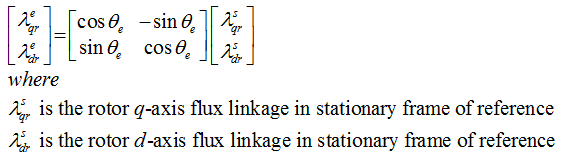
In direct FOC, the position of the synchronous reference frame (θe) is determined based on the values of q- axis and d- axis rotor flux linkages in the stationary reference frame. The relation of flux linkages in synchronous reference frame and stationary reference frame is
 |
(19) |
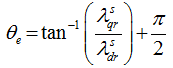
In order to achieve λeqr = 0, it is sufficient to define the position of the synchronous reference frame as
 |
(20) |
The difficulty with this approach is that λsqr and λedr are not directly measurable quantities. However, they can be estimated using direct measurement of air gap flux. To measure the air gap flux, hall-effect sensors are placed in the air gap and used to measure the air-gap flux in q-axis and d-axis. Since the hall-effect sensors are stationary, the flux measured by them is in stationary reference frame. The flux measured by the sensors is the net flux in the air gap (combination of stator and rotor flux). The net flux in the air gap is given by: