The equation 2 can be re-written as
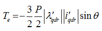 |
(3) |
The equation 3 is analogous to equation 1 . Hence, for a given magnitude of flux linkage, torque is maximised when the flux linkage and current vectors are perpendicular. Therefore, it is desirable to keep the rotor flux linkage perpendicular to rotor current vector.
In the analysis of FOC the following convention will be used:
- The parameters with a superscript “s ” are in stator frame of reference.
- The parameters with a superscript “e ” are in synchronous frame of reference.
- The parameters with subscript “ r ” indicate rotor parameters.
- The parameters with subscript “ s ” indicate stator parameters.
- All rotor quantities are referred to stator using the turns ratio of the windings (Lecture 17) and hence “ ' ” is dropped.
In case of singly excited IMs ( in singly excited IM, the rotor winding is not fed by any external voltage source. In case of wound rotor machines, they are short circuited using slip rings. For cage IMs, the rotor bars are short circuited at the terminals ), the rotor flux linkage vector and rotor current vector are always perpendicular. The voltage equations for the IM (refer to Lecture 19) in synchronous frame of reference are
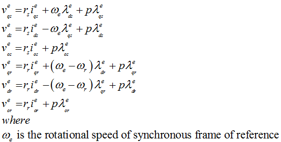 |
(1) |
In case of singly excited IM, the rotor voltages are zero, that is v e = 0, vdre = 0 and vore= 0 . Hence, the rotor currents can be obtained as
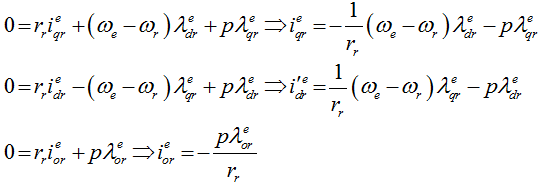 |
(2) |