Buck-Boost Converter Boundary between Continuous and Discontinuous Conduction
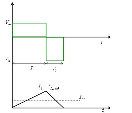
In Figure 10 the voltage and load current waveforms of at the edge of continuous conduction is shown. In this mode of operation, the inductor current (iL) goes to zero at the end of the off interval (T2). From Figure 10 , it can be seen that the average value of the inductor current is given by
![]() (38)
(38)
Substituting the value of ![]() from equation 36 into equation 38 gives:
from equation 36 into equation 38 gives:
![]() (39)
(39)
In terms of output voltage, equation 39 can be written as
![]() (40)
(40)
The average value of the output current is obained substituting the value of input current from equation 34 into equation 40 as:
![]() (41)
(41)
Most applications in which a buck-boost converter may be used require that Vout be kept constant. From equation 40 and equation 41 it can be seen that ILB and I0B result in their maximum values at D = 0 as
 (42)
(42)
From equation 38 it can be seen that peak-to-peak ripple current is given by
![]() (43)
(43)
|
Figure 10: Current and voltage waveforms of Buck Boost Converter in boundary between continuous and discontinuous mode |
Suggested Reading:
[1] M. H. Rashid, Power Electronics: Circuits, Devices and Applications , 3 rd edition, Pearson, 2004