Buck-Boost Converter
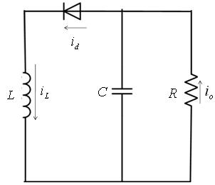
The general configuration of Buck-Boost converter is shown Figure 7. A buck-boost converter can be obtained by cascade connection of the two basic converters:
- • the step down converter
• the step up converter
The circuit operation can be divided into two modes:
- • During mode 1 (Figure 8a), the switch S1 is turned on and the diode D is reversed biased. In mode 1 the input current, which rises , flows through inductor L and switch S1.
• In mode 2 (Figure 8b), the switch S1 is off and the current, which was flowing through the inductor, would flow through L, C, D and load . In this mode the energy stored in the inductor (L) is transferred to the load and the inductor current (iL) falls until the switch S1 is turned on again in the next cycle.
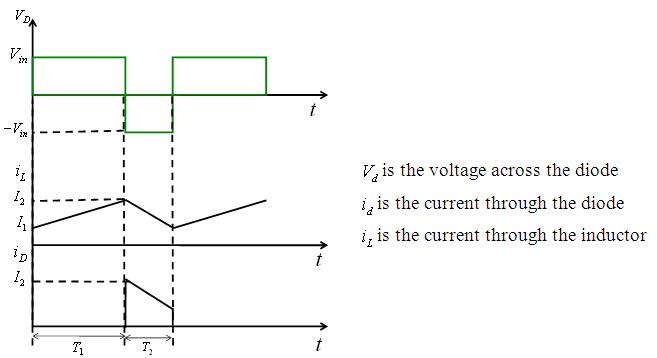
The waveforms for the steady-state voltage and current are shown in Figure 9.
|
|
Figure 8a: Buck Boost Converter in mode 1 |
Figure 8b: Buck Boost Converter in mode 2 |
|
|
Figure 9: Current and voltage waveforms of Buck Boost Converter |
|