Introduction
The topics covered in this chapter are as follows:
- • Principle of Step-Up Operation
• Boost Converter with Resistive Load and EMF Source
• Boost Converter with Filter and Resistive Load
• Buck-Boost Converter
Principle of Step-Up Operation (Boost Converter)
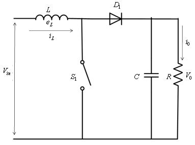
The circuit diagram of a step up operation of DC-DC converter is shown in Figure 1. When the switch S1 is closed for time duration t1, the inductor current rises and the energy is stored in the inductor. If the switch S1 is openerd for time duration t2, the energy stored in the inductor is transferred to the load via the didode D1 and the inductor current falls. The waveform of the inductor current is shown in Figure 2 .
|
|
Figure 1: General Configuration of a Boost Converter |
Figure 2: Inductor current waveform |
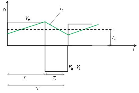
When the switch S1 is turned on, the voltage across the inductor is
![]() (1)
(1)
The peak to peak ripple current in the inductor is given by
![]() (2)
(2)
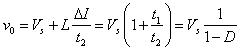
The average output voltage is
 (3)
(3)
From Equation 3 the following observations can be made:
- • The voltage across the load can be stepped up by varying the duty ratio D
• The minimum output voltage is Vs and is obtained when D = 0
• The converter cannot be switched on continupusly such that D = 1. For values of D tending to unity, the output becomes very sensitive to changes in D