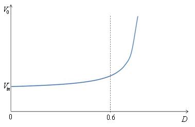
For values of D tending to unity, the output becomes very sensitive to changes in (Fig.3).
|
|
Figure 3: Output voltage vs. Duty ration for Boost Converter |
Figure 4: Boost converter with resistive load and emf source |
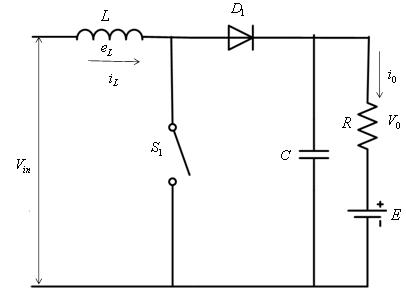
Boost Converter with Resistive Load and EMF Source
A boost converter with resistive load is shown in Figure 4 . The two modes of operation are:
Mode 1 : This mode is valid for the time duration
![]() (4)
(4)
where D is the duty ratio T is the switching period .
The mode 1 ends at t = DT.
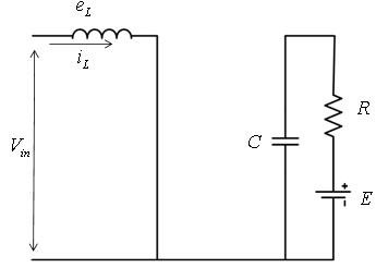
In this mode the switch S1 is closed and the equivalent circuit is shown in Figure 5 . The current rises throught the inductor L and switch S1. The current in this mode is given by
![]() (5)
(5)
Since the time instants involved are very small, the term ![]() . Hence, the solution of Equation 5 is
. Hence, the solution of Equation 5 is
![]() (6)
(6)
where I1 is the initial value of the current. Assuming the current at the end of mode 1( ![]() ) to be I2 (
) to be I2 ( ![]() ), the Equation 6 can be written as
), the Equation 6 can be written as
![]() (7)
(7)
|
|
Figure 5: Configuration of a Boost Converter in mode 1 |
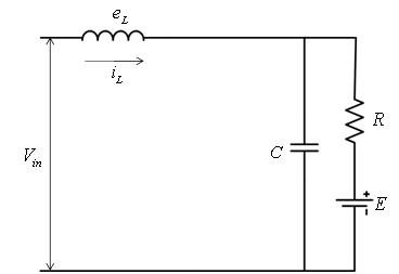
Figure 6: Configuration of a Boost Converter in mode 2 |