Mode2 : This mode is valid for the time duration
![]() (8)
(8)
In this mode the switch S1 is open and the inductor current flows through the RL load and the equivalent circuit is shown in Figure 6. The voltage equation in this mode is given by
![]() (9)
(9)
For an initial current of I2, the solution of Equation 9 is given by
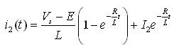 (10)
(10)
The current at the end of mode 2 is equal to I1:
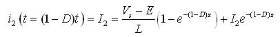 (11)
(11)
were Z = TR/L
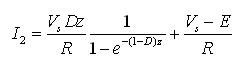
Solving Equation 7 and Equation 11 gives the values of I1 and I2 as
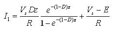 (12)
(12)
 (13)
(13)
The ripple current is given by
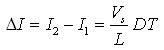 (14)
(14)
The above equations are valid if ![]() . In case
. In case ![]() , the converter works in discontinuous mode.
, the converter works in discontinuous mode.
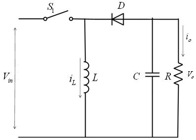
Boost Converter with Filter and Resistive Load
A circuit diagram of a Buck with filter is shown in Figure 7. Assuming that the inductor current rises linearly from I1 to I2 in time t1
![]() (15)
(15)
|
Figure 7: Configuration of a Buck Boost Converter |