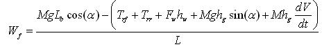
The first term on the right side is the total tractive effort and the second term is the total tractive resistance. To determine the maximum tractive effort, that the tire ground contact can support, the normal loads on the front and rear axles have to be determined. By summing the moments of all the forces about point R (centre of the tire-ground area), the normal load on the front axle Wf can be determined as
 (18)
(18)
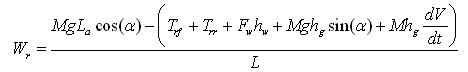
Similarly, the normal load acting on the rear axel can be expressed as
 (19)
(19)
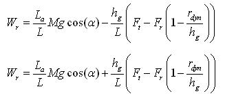
In case of passenger cars, the height of the centre of application of aerodynamoic resistance (hw) is assumed to be near the height of centre of gravity of the vehicle (hg). The equation18 and 19 can be simplified as
 (20)
(20)
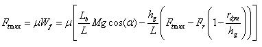
and
 (21)
(21)
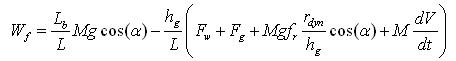
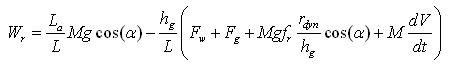
Using equation 5, equation 17, equation 20 and 21 can be rewritten as
 |
(22) |
| (23) |
The first term on the right hand side of equation 22 and equation 23 is the static load on the front and the rear axles when the vehicle is at rest on level ground. The second term is the dynamic component of the normal load.
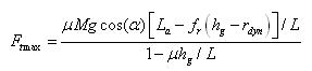
The maximum tarctive effort (Ftmax) ) that the tire-ground contact can support is described by the product of the normal load and the coefficient of road adhesion ( m ). In Table 3, the values of coefficient of adhesion are given for different speeds of the vehicle and different road conditions. For the front wheel driven vehicle, Ftmax is given by
 (24)
(24)
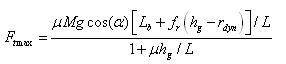 (25)
(25)
For the rear wheel driven vehicle, Ftmax is given by
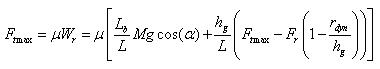 (26)
(26)
 (27)
(27)