The torque relation between the drive wheels and the ICE is
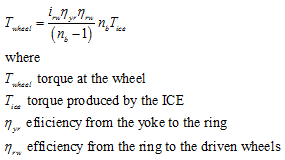 |
(2) |
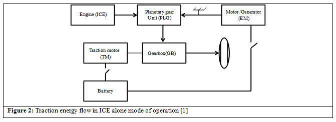
b. • EM alone traction: In this mode, the ICE is shut down, the clutch is engaged and lock1 releases the sun gear and the shaft of the EM from the stationary frame. The lock 2 locks the yoke to the stationary frame. In this mode the vehicle is propelled by the EM alone. The energy path is shown in Figure 3 . The speed and torque relation between the EM and the driven wheel is ( refer Table 1 Lecture 8 )
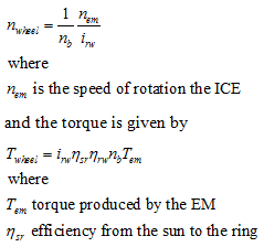 |
(3) |
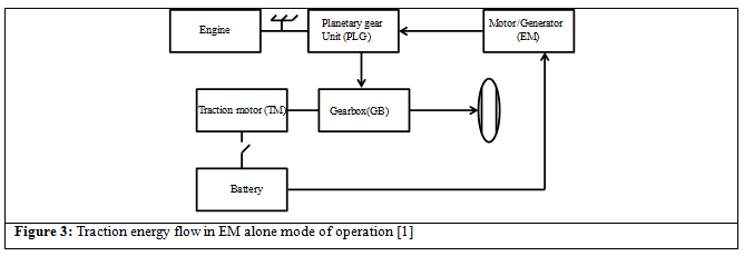
c. ICE and EM operation with speed coupling: In this mode of operation the clutch is engaged and the locks 1 and 2 are released. The energy flow path is shown in Figure 4 . The power from the ICE and the EM is transferred to the driven wheels via the planetary gear. Hence, the speed of the driven wheel is (refer equation 7 Lecture 8 ):
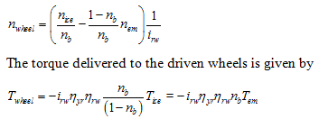 |
(4)
(5) |