At ![]() rad/sec, the magnitude is
rad/sec, the magnitude is ![]() dB. To make
this as the actual gain crossover frequency, lag part should provide
an attenuation of
dB. To make
this as the actual gain crossover frequency, lag part should provide
an attenuation of ![]() dB at high frequencies.
dB at high frequencies.
Thus,
which gives
![]() . Now,
. Now, ![]() should be placed much
below the new gain crossover frequency to retain the desired PM. Let
should be placed much
below the new gain crossover frequency to retain the desired PM. Let
![]() be
be ![]() . Thus
. Thus
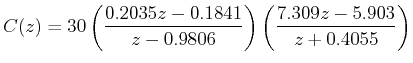
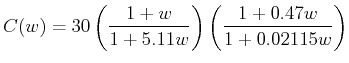
The overall compensator is
The frequency response of the system after introducing the above
compensator is shown in Figure 7, which shows that the
desired performance criteria are met.
![\includegraphics[width=4.5in]{m5l8fig7.eps}](images/img67.png)
Re-converting the controller in z-domain, we get