Since the new ωg should be 10 rad/sec, the required additional phase at ωg, to maintain the specified PM, is 45 - (180 - 198) = 63° . With safety margin 2°,
And
which gives ![]() . However, introducing this compensator will actually increase the gain crossover frequency where the phase characteristic will be different than the designed one. This can be seen from Figure 3.
. However, introducing this compensator will actually increase the gain crossover frequency where the phase characteristic will be different than the designed one. This can be seen from Figure 3.
![\includegraphics[width=5.0in]{m5l8fig3.eps}](images/img31.png) |
Figure 3: Frequency response of the system in Example 1 with only a lead compensator
The gain crossover frequency is increased to 23.2 rad/sec. At 10 rad/sec, the phase angle is -134° and gain is 12.6 dB. To make this as the actual gain crossover frequency, lag part should provide an attenuation of -12.6 dB at high frequencies.
At high frequencies the magnitude of the lag compensator part is ![]() . Thus ,
. Thus ,
![]()
which gives ![]() . Now,
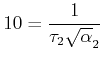
. Now, ![]() should be placed much below the new gain crossover frequency to retain the desired PM. Let
should be placed much below the new gain crossover frequency to retain the desired PM. Let ![]() be 0.25. Thus
be 0.25. Thus
![]()
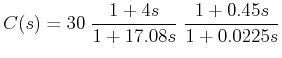
The overall compensator is