1.1 Lag-lead compensator design
Example 1 Consider the following system with transfer function
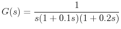
Design a lag-lead compensator C(s) such that the phase margin of the compensated system is at least 45° at gain crossover frequency around 10 rad/sec and the velocity error constant Kv is 30.
The lag-lead compensator is given by
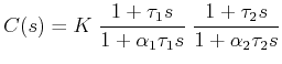 where,
 ![]()
When ![]()
![]()
Thus K = 30 . Bode plot of the modified system KG(s) is shown in Figure 2. The gain crossover frequency and phase margin of KG(s) are found out to be 9.77 rad/sec and -17.2° respectively.
![\includegraphics[width=5.0in]{m5l8fig2.eps}](images/img22.png) |
Figure 2: Bode plot of the uncompensated system for Example 1
Since the PM of the uncompensated system with K is negative, we need a lead compensator to compensate for the negative PM and achieve the desired phase margin.
However, we know that introduction of a lead compensator will eventually increase the gain crossover frequency to maintain the low frequency gain.
Thus the gain crossover frequency of the system cascaded with a lead compensator is likely to be much above the specified one, since the gain crossover frequency of the uncompensated system with K is already 9.77 rad/sec.
Thus a lag-lead compensator is required to compensate for both.
We design the lead part first.
From Figure 2, it is seen that at 10 rad/sec the phase angle of the system is -198°.