Phase angle at ωg = 3.1 is -90 - tan -1 3.1 = - 162° . Thus the PM of the uncompensated system with K is 18°.
If it was possible to add a phase without altering the magnitude, the additional phase lead required to maintain PM= 45° is 45° - 18° = 27° at ωg = 3.1 rad/sec.
However, maintaining same low frequency gain and adding a compensator
would increase the crossover frequency. As a result of this, the
actual phase margin will deviate from the designed one. Thus it is
safe to add a safety margin of ε to
the required phase lead so
that if it devaites also, still the phase requirement is met. In general ε
is chosen between 5° to 15°.
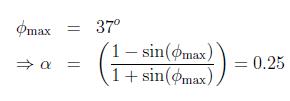
So the additional phase requirement is 27° + 10° = 37° , The lead part of the compensator will provide this additional phase at ωmax .
Thus
The only parameter left to be designed is τ. To find τ, one should locate the frequency at which the uncompensated system has a logarithmic magnitude of 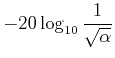 .
.
Select this frequency as the new gain crossover frequency since the compensator provides a gain of 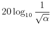 at ωmax. Thus
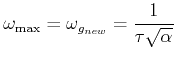
In this case ωmax = ωg new = 4.41 . Thus
The lead compensator is thus
With this compensator actual phase margin of the system becomes 49.6° which meets the design criteria.
The corresponding Bode plot
is shown in Figure 2
![\includegraphics[width=4.in]{m5l6fig1c.eps}](images/img61a.png)