1 Compensator Design Using Bode Plot
In this lecture we would revisit the continuous time design techniques using frequency domain since these can be directly applied to design for digital control system by transferring the loop transfer function in ![]() -plane to
-plane to ![]() -plane.
-plane.
1.1 Phase lead compensator
If we look at the frequency response of a simple PD controller, it is evident that the magnitude of the compensator continuously grows with the increase in frequency.
The above feature is undesirable because it amplifies high frequency noise that is typically present in any real system.
In lead compensator, a first order pole is added to the denominator of the PD controller at frequencies well higher than the corner frequency of the PD controller.
A typical lead compensator has the following transfer function.
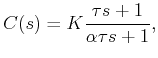 where,
 ![]()
![]() is the ratio between the pole zero break point (corner) frequencies.
is the ratio between the pole zero break point (corner) frequencies.
Magnitude of the lead compensator is 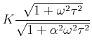 . And the phase contributed by the lead compensator is given by
![]()
Thus a significant amount of phase is still provided with much less amplitude at high frequencies.
The frequency response of a typical lead compensator is shown in Figure 1 where the magnitude varies from ![]() to
to  and maximum phase is always less than 90° (around 60° in general).
![\includegraphics[width=5.2in]{m5l6fig1.eps}](images/img12.png) |
Figure 1: Frequency response of a lead compensator