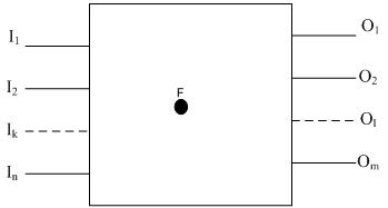
Figure 3. Block diagram of a circuit with a fault at point F
Figure 3 illustrates block diagram of a circuit with n inputs, m outputs and a fault at net F. Let the following Boolean functions hold
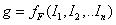 be the function for the Boolean value at net F (in terms of all the inputs)
 be the functions for output lines 01 to 0m, under failure at point F. It may be noted that without fault all the output lines are functions of the inputs. With the failure, the output lines are functions of the inputs and the Boolean value at point F.
Now, Boolean difference, or Boolean partial derivative, of the circuit block output  with respect to g is:

For detecting s-a-0 fault at location F, we need


The equations mean the following.
The first equation requires that to test a stuck-at-0 fault at F, 1 should be applied at F (sensitization). Second equation says that in order to detect the fault, there is at least one output such that the Boolean difference of the output with respect to F must be 1 (i.e., the output must change when the signal at F changes from 1 to 0.)
Similarly, for detecting s-a-1 fault at location F, we need


Unfortunately, due to high complexity the Boolean difference is not an efficient way to compute test patterns for large circuits.
4.4 Path sensitization
As discussed in the last module, ATPG by path sensitization method is generally applied for “difficult to test faults” and comprises three phases.
- Fault sensitization: In this step a stuck-at fault is activated by setting the signal driving the faulty net to an opposite value from the fault value.
- Fault propagation: In this step a path is selected from the fault site to some primary output, where the effect of the fault can be observed for its detection.
- Line justification: In this step the signals in (internal) nets or some primary inputs, which were assigned for fault sensitization/propagation, are justified by setting (remaining) primary inputs of the circuit.
In the second and third steps, a conflict may occur, where a necessary signal assignment contradicts some previously-made assignment. When conflicts occur we need to take a new alternative path for fault propagation and see if all signals can be justified.
We have seen some simple examples for ATPG using the path sensitization (sensitization-propagation-justification) approach in the last module. Now we will see a bit more complex example of ATPG using the path sensitization approach. However, instead of using Boolean algebra (as in last module), we will use Roth’s 5 valued algebra. Following that, in the next lecture we will learn D-algorithm--the primary and formal algorithm for ATPG using path sensitization.