1. Introduction
In the last module we saw that in a circuit some faults are “easy to test” and some others are “difficult to test”. Further, we have also seen an algorithm that can estimate the “easy to test faults” and the ones that are “difficult to test”. Fault simulation algorithms are used to determine test patters for easy to test faults and for the others, sensitization–propagation -justification approach is used. In the last module we also discussed in detail, most of the commonly used fault simulation algorithms. In this module we will study automatic test pattern generation (ATPG) using sensitization–propagation -justification approach. We will first introduce the basics of ATPG and ATPG algebras. Following that in the next lecture of the module we will present D-algorithm--the basic and first ATPG algorithm developed. Also, we will present basics of some other advanced ATPG algorithms, which were successors of the D-algorithm.
2. What is ATPG
ATPG stands for automatic test pattern generation. As the name suggests, ATPG procedure involves generation of input patterns that can ascertain presence or absence of fault(s) at some location(s) in a circuit. There are several ways of ATPG. In the last module we have seen two of them- (i) fault simulation and (ii) sensitization–propagation –justification. These techniques are based on Boolean logic manipulations and are most widely used. However, it must not be felt that only logic based schemes can be used for ATPG. Here we briefly discuss another interesting ATPG technique that requires thermal imaging technique [1]. Thermal imaging technique involves taking images of the silicon (of the circuit) and then drawing conclusions based on temperature profile of various regions of the silicon. In case of ATPG based on imaging technique, one needs to find an input pattern that results in difference of temperature at a location (which is being tested) with and without fault. For example, when a net say A, has stuck-at-0 fault and primary inputs are applied such that net A gets 1, then temperature in A will be abnormally higher, due to high short circuit current. The advantage is, we need not have to worry about propagating the effect of the fault to primary outputs, as all internal points are observable in terms of temperature profile. So, sensitization is enough to generate a test pattern. However, the instrumentation cost for thermal imaging is high. So, widely used ATPG algorithms are based on logic manipulations. Henceforth, when we talk about ATPG it will imply techniques based on logic operations. Next we will see basics of ATPG algebra, which will be required to understand D-algorithm.
3. ATPG algebra
As we all know, Boolean algebra comprising of 0 and 1, is used for studying behavior of digital circuits. However, if we consider circuits with fault, then Boolean algebra will not suffice to represent signal values. Let us take an example. Consider the AND gates given in Figure 1. In order to represent that I1=1,I2=1 detects s-a-0 fault at the output, we need to mark O1 as 1/0-indcating that under normal condition O1 is 1 and under fault it is 0. Similarly, in case of Figure 1(b) we need to mark O1 as 0/1--indicating that under normal condition O1 is 0 and under fault it is 1. So we can see that a single bit (0 or 1) is not enough for representing and studying circuits with fault.
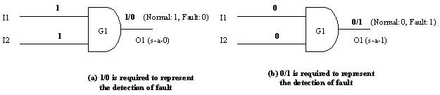
Figure 1. Requirement of more than Boolean (0/1) algebra for studying fault behaviors
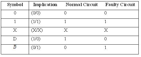
So, the algebra suitable for studying circuits with fault should have higher-order notations than Boolean algebra. In other words, we need more notations than just 0 and 1 for representing both the “good” and the “failing” circuit simultaneously. Roth [2] proposed a five valued algebra which suitable for ATPG based on sensitize-propagate-justify approach. Table 1 illustrates Roth’s 5-valued algebra.
Table 1. Roth’s five value algebra