In general, for models of synchronous systems, the transition relation is a conjunction of formulas representing the individual components of the system, since the transitions of the components are simultaneous . The outputs of the state machine can be given as Boolean functions of the inputs and registers.
5.2 Asynchronous Sequential Circuits
In an asynchronous state machine, there is no global clock to which all state changes are synchronized. This makes designing correct asynchronous circuits considerably more challenging than designing correct synchronous circuits. There are two plausible models of asynchronous state machines
• Simultaneous Model
• Interleaving Model
In simultaneous model, any or all state variables may change state in a given transition. Each state component makes an independent and non-deterministic choice regarding whether to change value or not. Let X, X' and f be defined in the same way as that of synchronous state machines. Then, the transition relation for simultaneous model can be presented by a formula in the following form.
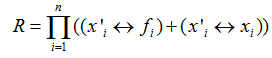
For any transition and any state variable xi, either the new value of xi (i.e., x'i) is determined by fi, or it is the same as the old value. Note that this differs from the synchronous model in which every state variable is revaluated at every transition.
In interleaving model, only one state component changes value in a given transition. It is non-deterministic to choose the state changing its component. The transition relation for interleaving model can be presented by a formula in the following form
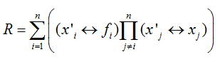
In any transition, for some state variable xi, the new value x'i is determined by fi and the remaining variables keep their old value. Note that in this case, the transition relation is represented by a disjunction of component relations rather than a conjunction.
Let us take a simple synchronous sequential circuit of MOD-6 Counter. The counting sequence is: 0-1-2-3-4-5-0....... The state transition graph of MOD-6 counter is shown in Figure 6. The circuit diagram of MOD-6 counter is given in Figure 7. The transition formula for MOD-6 counter is:
![]() OBDD for this transition relation of MOD-6 counter is shown in Figure 8 (for ordering
OBDD for this transition relation of MOD-6 counter is shown in Figure 8 (for ordering ![]()
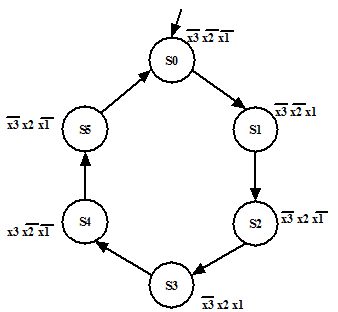
Figure 6. State transition graph of MOD-6