1. Introduction
In the last three lectures, we have seen that we can represent all Boolean functions by ROBDDs. Combinational circuits can directly be expressed as a Boolean expression and so we can obtain an ROBDD for them. In combinational circuit, the output depends on the input of the circuit. In sequential circuits, the outputs depend on current input and the previous outputs (states). So the Boolean expressions representing sequential circuits have two copies of output variables, one representing the current output and the other copy representing the previous output. Sequential circuits are expressed with the help of state transition diagrams. In the case of sequential circuits, we have some inputs, some outputs and some state variables. The state variables can either represent current states or next states. The next state depends on current state and input variables. Thus, the next states can be represented by OBDDs. Even the transitions can be represented by OBDDs. Thus, we can represent all sequential circuits with the help of OBDDs. In this lecture, we will discuss OBDDs for sequential circuits.
2. Representing subsets of sets of states using OBDDs
Figure 1 shows the state transition graph (STG) for a sequential circuit.
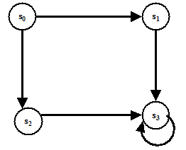
Figure 1. An example of STG of a sequential circuit
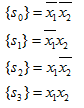
Here, the states s 0, s 1, s 2 and s 3 can be distinguished using two state variables, say X1 and X 2 . Let us represent them as follows.
............................................................
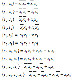
Since we use Boolean functions to represent subsets, we can represent all the subsets of states ( s 0, s 1, s 2 and s 3 ) using OBDDs. The sub-sets of states in terms of Boolean function are as follows.