The example given in Figure 5 through Figure 7 illustrates the working of apply Algorithm. Figure 5 illustrates two ROBDDs which are ORed. Figure 6 illustrates the steps of the apply algorithm. Figure 7 illustrates the final OBDD after reduction; the result of apply( +, Bf, Bg ) may not be reduced one.
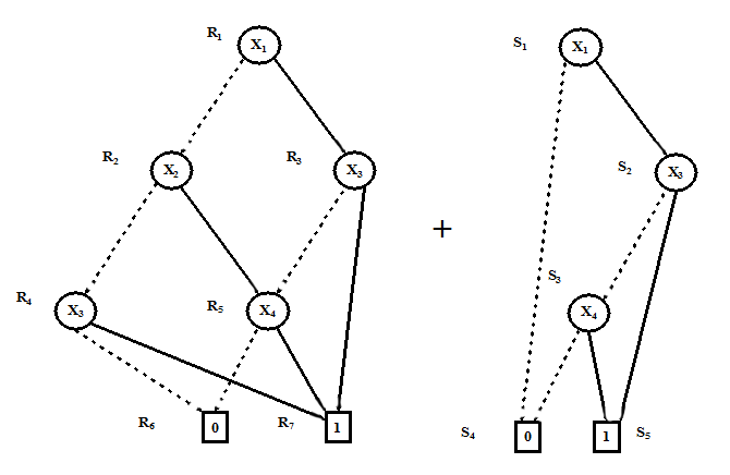
......................................Figure 5. OR of two ROBDD's with ordering [X1 ,X2 ,X3 ,X4 ]
Now we discuss construction of some of the nodes of the final OBDD shown in Figure 6 vis-a-vis steps of the apply algorithm. Construction of other nodes can be explained in a similar fashion.
• x1 (R1 ,S1 ): According to Step-2 on R1 and S1 --create an xi-node n (called rf, r g =R1 ,S1 ).
• x2 (R2 ,S4 ): According to Step-2 on x 1 (R1 ,S 1 ) -- If both nodes (R1 ,S1 in x1 ) are xi -nodes create dashed line from x1 to apply ( op , lo( rf ) , lo( rg ) ) = apply ( op , lo( R1) , lo( S1 ) ) = apply (OR, R2 ,S4 ), which is node x2.
• x4 (R4 ,S 4 ): According to Step-3 on x2 (R2 ,S4 ) -- If r f (R 2 in x 2 ) is an xi -node, but r g (S4 in x 2 ) is a terminal node or an xj -node with j > i , create an x i -node n (called r f, r g=x 2 ) with a dashed line to apply ( op , lo( rf ) , r g ) =(OR,R 4 ,S4 ), which is node x 4.
• Terminal node (R6 ,S4 ): According to Step-3 on x 4 (R4 ,S4 )-- If r f (R 4 in x 4 ) is an x i -node, but rg (S4 in x4 ) is a terminal node or an xj-node with j > i , create an xi -node n (called r f, r g=x4 ) with a dashed line to apply ( op , lo( rf ) , r g ) =(OR,R6 ,S4 ), which is Terminal node (R6 ,S4 ) . The value of
R 6 ,S4 is 0; apply (OR, R6 =0,S 4 =0)=0.
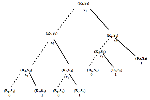
.....................Figure 6. Steps of the apply algorithm for the example of Figure 5