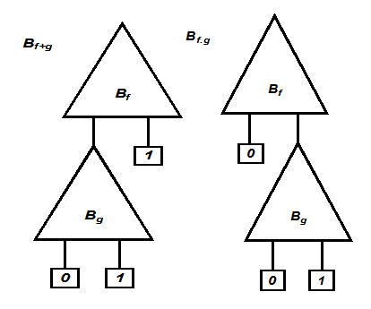
..............................Figure 4. the BDDs for the function ( f + g ) and ( f . g )
Figure 4 shows the BDDs for the function ( f + g ) and ( f . g ). The construction procedure is simple. In case of “f + g ” if f is 1, then we need not evaluate g and if fis “0” the final result depends only on g . This is reflected in the final BDD for “ f + g ”. Similarly, in case of “ f. g ” if f is 0, then we need not evaluate g and if fis “1” the final result depends only on g . This is reflected in the final BDD for “f . g ”. The way we are constructing the BDDs for OR and AND operation, it is clear that the resultant BDDs are not ordered or reduced.
So, we need a method where the resultant BDD (after Boolean operations on ROBDDs) is also a ROBDD.
2.1 Binary Operations on ROBDD to procedue ROBBD
To perform the binary operation on two ROBDD's Bfand Bg , corresponding to the functions f and g respectively, we use the algorithm apply( op, Bf, Bg ). The two ROBDDs Bf and Bg have compatible ordering.
Application of apply( op, Bf, Bg ) will give a OBDD. The ordering of the resultant BDD is same as Bf or Bg but it may not be the reduced one. After constructing the resultant BDD, we may apply the reduce algorithm to get the ROBDD.
The function apply is based on the Shannon's expansion for f and g :
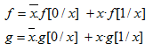
From the Shannon's expansion of f and g :
![]()
This is used as a control structure of apply which proceeds from the roots of Bf and Bgdownwards to construct nodes of the OBDD Bf op Bg. Let r f be the root node of Bf and r g be the root node of Bg.
apply( op, Bf, Bg ) Algorithm :
1. If both rfand r g are terminal nodes with labels lf and lg, respectively
compute the value lf op lg and the resulting OBDD is B 0 if the value is 0 and B 1 otherwise.
In the remaining cases, at least one of the root nodes is a non-terminal.
2. If both nodes are xi -nodes (i.e., non-terminal of same order),
create an xi -node n (called rf, rg) with a dashed line to apply ( op , lo( rf ) , lo( rg ) ) and a solid line to apply ( op , hi( rf ) , hi( rg) ).
3. If r f is an xi -node, but rg is a terminal node or an xj -node with j > i ,
create an xi -node n (called rf, rg ) with a dashed line to apply ( op , lo( rf ) , rg ) and a solid line to apply (op , hi( rf ) , rg).
4. The case in which rgis a non-terminal node, but rfis a terminal or an xj -node with
j > i , is handled symmetrically to case 3.