Satellites
have highly precise oscillators with a fundamental frequency
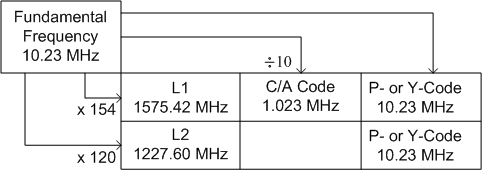
of 10.23 MHz. Satellite signals basically consists of 3 componnts
(Figure 6.2):
Two micro wave L-band (also called Carrier) waves
L1 carrier: 1575.42 MHz
L2 carrier: 1227.60 MHz
Ranging codes modulated on the carrier waves
C/A code, the clear/access or coarse/acquisition code modulated at 1.023 MHz, degraded code for civilian users, modulated on L1 only
P (Y) code, the private, protected, or precise code
modulated at 10.23 MHz. It is modulated on both L1 and
L2 carrier waves, for authorized military users
Navigation message
Modulated on both L1 and L2 and contains satellite positions
and constants
Two different frequencies are used to eliminate errors introduced by ionospheric refraction.
Figure 6.2 GPS signal structure
All frequencies derived from
the fundamental frequency ( f = 10.23 MHz) with the
following frequencies and wavelengths
L1 =
154f = 1575.42 MHz, wavelength of 19.0
cm,
L2 =
120 f = 1227.60 MHz, wavelength of 24.4 cm
C/A code =
(1/10 f ) = 1.023 MHz (Mega bits per second Mbps), wavelength
of 293.1 m, period of 1 millisecond
P code =
10.23 MHz, wavelength of 29.31 m, period of 266 days; 7 days/satellite
Navigation code = 50 bits per second (bps), data signal
cycle length of 30 seconds
The structure of GPS carrier signals, codes and their combinations
is quite complex. Since the carriers
are pure sinusoids, they cannot be used easily for instantaneous
positioning purposes and therefore two codes are modulated
onto them: the C/A (coarse acquisition) code and P (precise)
code.
The
codes (P and C/A) are nothing but binary sequence of information
generated by a complicated algorithm.
For purposes of imposing
these binary data onto the carriers, all of the codes are transferred from the
0 and 1 states to the -1 and 1 status respectively. Figure 6.3 shows how both
code and carrier are combined in L1 signal (Sickle, 2001).
The technique is called binary biphase modulation (alternatively
binary phase shift keying BPSK). For more details on signal
structure one can refer to Seeber (2003), Sickle (2001) and
Parkinson et al. (1996).