| |
| | |
|
There are some considerations to be taken into account before designing and
installing a ramp meter.
Installation of a ramp meter to achieve the desired objectives requires
sufficient room at the entrance ramp.
The determination of minimum ramp length to provide safe, efficient, and
desirable operation requires careful consideration of several elements
described below:
- Sufficient room must be provided for a stopped vehicle at the meter to
accelerate and attain safe merge speeds.
- Sufficient space must be provided to store the resulting cyclic queue of
vehicles without blocking an upstream signalized intersection.
- Sufficient room must be provided for vehicles discharged from the upstream
signal to safely stop behind the queue of vehicles being metered.
Provision for the distances mentioned is an integral part of ramp design.
Figure 1 illustrates the requirements for the different types
of distances explained above.
Sufficient stopping distance is required to be provided prior to entry to the
ramp.
Motorists leaving an upstream signalized interchange will likely encounter the
rear end of a queue as they proceed toward the meter.
Adequate maneuvering and stopping distances should be provided for both turning
and frontage road traffic.
This stopping distance calculated similar to the stopping sight distance which
is a combination of the brake distance and lag distance travelled by a vehicle
before stopping.
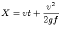
The equation to calculate the minimum stopping distance is given below:
 |
(1) |
where, X is the stopping distance in meters, v is the velocity of the vehicle
in m/sec, t is the time in seconds, g is the gravity coefficient in
 , f is the friction coefficient.
This is the minimum distance to be provided from the back of the queue for safe
stopping of vehicles approaching the ramp. , f is the friction coefficient.
This is the minimum distance to be provided from the back of the queue for safe
stopping of vehicles approaching the ramp.
Figure 1:
Components of Ramp design criteria
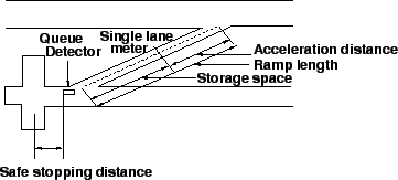 |
Figure 1 shows Safe stopping distance, storage distance
and acceleration distance which are respective three criteria for ramp design.
The storage distance is required to store the vehicles in queue to a ramp
meter.
The queue detector controls the maximum queue length in real-time.
Thus, the distance between the meter and the queue detector defines the storage
space.
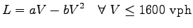
The following generalized spacing model can be used to determine the
single-lane
storage distance:
 |
(2) |
In this equation, L (in meters) is the required single-lane storage distance on
the ramp when the expected peak-hour ramp demand volume is V vph and a, b are
constants.
This figure shows the requirements for three metering strategies:
- Single-lane with single vehicle release per cycle.
- Single-lane with bulk metering (three vehicles per green).
- Dual-lane metering assuming single-line storage.
Figure 2:
Variation of distance to meter with Ramp demand volume for different
strategies of Ramp metering
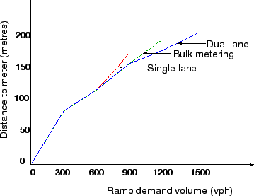 |
In the Figure 2 the curve is shown for the variation of storage
distance i.e. distance to meter with ramp demand volume for different strategy
used for Ramp metering.
The distance from meter to merge is provided so that vehicles can attain a suitable merging speed after being discharged from the ramp meter.
AASHTO provides speed-distance profiles for various classes of vehicles as they
accelerate from a stop to speed for various ramp grades.
Figure 3, given below provides similar acceleration distances
needed to attain various freeway merging speeds based on AASHTO design criteria.
Figure 3:
Acceleration length v/s merge speed for different strategies of Ramp
metering
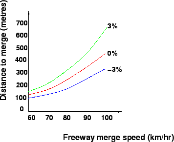 |
Table 1 provides the acceleration length for different merge speed and with
ramps of different grade.
The desired distances to merge increases with increasing freeway merge speed and
the same ramp grade.
Table 1:
Acceleration length of ramps
| Merge speed |
Ramp Grade (%) |
| (kmph) |
-3 |
0 |
+3 |
| 60 |
90 |
112 |
150 |
| 70 |
127 |
158 |
208 |
| 80 |
180 |
228 |
313 |
| 90 |
248 |
323 |
466 |
| 100 |
331 |
442 |
665 |
|
|
| | |
|
|
|