Magnetic Junctions :
The transport between two metallic electrodes can be in general classified into two types as displayed schematically in Figure 27.2: One type of junction is tunnel junction, where the separation between the electrodes varies from few to few tens of angstroms and the other is a contact type, where the contacts are made at some points selectively .
(1) When the separation between the electrodes exceeds a few angstroms, electrons move between them through tunnelling. The probability that any one electron tunnels through a barrier of height V and length l is given by:
|
(27.2) |
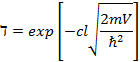
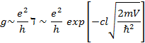
where c is a constant of order unity, which depends on the detailed shape of the barrier and on the electronic wavefunctions. The barrier can be either (i) the vacuum created between the two electrodes, in which case the height of the barrier is given by the work function of the electrodes, or (ii) by inserting an insulating layer between the two electrodes, as shown in Figure 27.1. The barrier height in the latter case depends on the position of the edges of the gap of the insulating material with respect to the Fermi level of the electrodes. It is clear from the eqn.(27.2) that the tunnelling depends exponentially on the distance between the electrodes, and we may expect that in a junction of macroscopic size, the current will be due to tunnelling events at bulging of the interface. A change of a few angstroms even can greatly modify the tunnelling probability. The conductance at any of these points is given by:
|
(27.3) |
(2) On the other hand, the two electrodes can be in contact in some points. Then, the conductance of each contact is given by e2 /h times the number of electron channels through the contact. It is roughly given by the cross section of the contact expressed in units of inverse square Fermi wavevector ( ![]() ). Then,
). Then,
|
(27.4) |
where A is the area of the junction.