5. Relief valve
Relief valve is the simplest type of pressure regulating device. The schematic of its construction and working is shown in the Figure 6.3.8. It is used as a backup device if the main pressure control fails. It consists of ball type valve held on to the valve seat by a spring in tension. The spring tension can be adjusted by using the adjusting cap. When the air pressure exceeds the spring tension pressure the ball is displaced from its seat, thus releasing the air and reducing the pressure. A relief is specified by its span of pressure between the cracking and full flow, pressure range and flow rate. Once the valve opens (cracking pressure), flow rate depends on the excess pressure. Once the pressure falls below the cracking pressure, the valve seals itself.
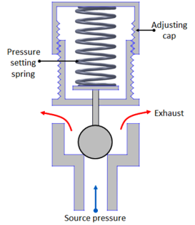
Fig. 6.3.8 Relief valve
6. Non-relieving pressure regulator
In a non-relieving pressure regulator (Fig. 6.3.9) the outlet pressure is sensed by a diaphragm which is preloaded by a pressure setting spring. If outlet pressure is too low, the spring forces the diaphragm and poppet to move down thus opening the valve to admit more air and raise outlet pressure. If the outlet pressure is too high the air pressure forces the diaphragm up hence reduces the air flow and causing a reduction in air pressure. The air vents away through the load. At steady state condition the valve will balance the force on the diaphragm from the outlet pressure with the preset force on the spring.
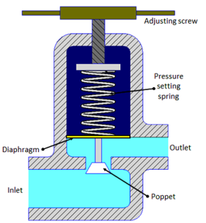
Fig. 6.3.9 Non-relieving type pressure regulator