3. Lubricators
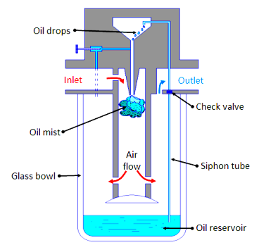
Fig. 6.3.6 Air lubricator
The compressed air is first filtered and then passed through a lubricator in order to form a mist of oil and air to provide lubrication to the mating components. Figure 6.3.6 shows the schematic of a typical lubricator. The principle of working of venturimeter is followed in the operation of lubricator. The compressed air from the dryer enters in the lubricator. Its velocity increases due to a pressure differential between the upper and lower changer (oil reservoir). Due to the low pressure in the upper chamber the oil is pushed into the upper chamber from the oil reservoir through a siphon tube with check valve. The main function of the valve is to control the amount of oil passing through it. The oil drops inside the throttled zone where the velocity of air is much higher and this high velocity air breaks the oil drops into tiny particles. Thus a mist of air and oil is generated. The pressure differential across chambers is adjusted by a needle valve. It is difficult to hold an oil mixed air in the air receiver as oil may settle down. Thus air is lubricated during secondary air treatment process. Low viscosity oil forms better mist than high viscosity oil and hence ensures that oil is always present in the air.