The hydraulic systems consists a number of parts for its proper functioning. These include storage tank, filter, hydraulic pump, pressure regulator, control valve, hydraulic cylinder, piston and leak proof fluid flow pipelines. The schematic of a simple hydraulic system is shown in figure 5.1.2. It consists of:
- a movable piston connected to the output shaft in an enclosed cylinder
- storage tank
- filter
- electric pump
- pressure regulator
- control valve
- leak proof closed loop piping.
The output shaft transfers the motion or force however all other parts help to control the system. The storage/fluid tank is a reservoir for the liquid used as a transmission media. The liquid used is generally high density incompressible oil. It is filtered to remove dust or any other unwanted particles and then pumped by the hydraulic pump. The capacity of pump depends on the hydraulic system design. These pumps generally deliver constant volume in each revolution of the pump shaft. Therefore, the fluid pressure can increase indefinitely at the dead end of the piston until the system fails. The pressure regulator is used to avoid such circumstances which redirect the excess fluid back to the storage tank. The movement of piston is controlled by changing liquid flow from port A and port B. The cylinder movement is controlled by using control valve which directs the fluid flow. The fluid pressure line is connected to the port B to raise the piston and it is connected to port A to lower down the piston. The valve can also stop the fluid flow in any of the port. The leak proof piping is also important due to safety, environmental hazards and economical aspects. Some accessories such as flow control system, travel limit control, electric motor starter and overload protection may also be used in the hydraulic systems which are not shown in figure 5.1.2.
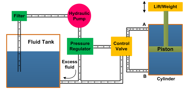
Figure 5.1.2 Schematic of hydraulic system
(Click here to watch the video showing various components of a hydraulic system.)