2.2 Integral Controller
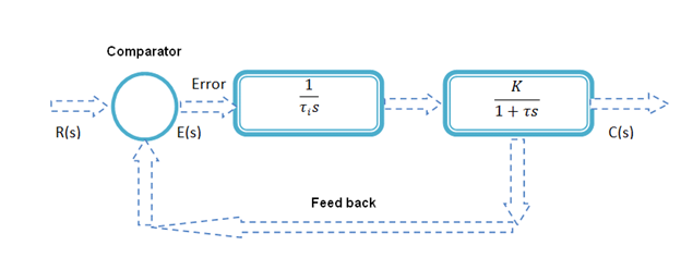
Figure 3.4.5 A I-Controller
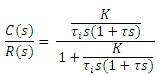
In an integral controller, the manipulation equals the integral of the error over time, multipled by a gain KI (Eq. 3.4.1). Figure 3.4.5 shows the block diagram of Integral controller empolyed for a SISO system. The closed loop transfer function can be written as,
 |
(3.4.7.) |
| (3.4.8.) |
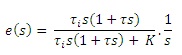
For a Step input, R(s) = 1/s, we get the steady state error as,
 |
(3.4.9.) |
| (3.4.10.) |
Effect of adding Integral Controller in system:
The step response of this closed loop system with integral action is shown in figure 3.4.6. The integral term enhances the movement of the process towards desired point. It also eliminates the residual steady-state error that produces with a pure proportional controller. From the transfer function, it is observed that use of integral controller leads to increasing order of closed loop system which may cause instability, slow and oscillatory response. However the system has a major advantage that integral controller produces zero steady state error.
The drawbacks of integral controller can be rectified if we use Proportional controller along with Integral one.
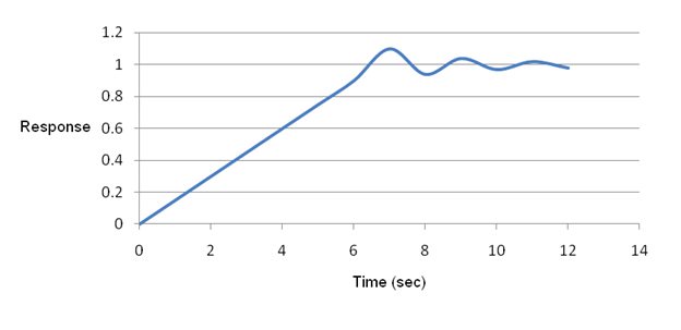
Figure 3.4.6 Response using a Integral controller