As an example for ![]() = 1 we get
= 1 we get ![]() = 0.5, etc. and it will result in Figure 6.18. Similar plots can be obtained for other value of μ and
= 0.5, etc. and it will result in Figure 6.18. Similar plots can be obtained for other value of μ and ![]() (i.e., other discs and other shafts) with different boundary conditions. It is seen in Figure 5.31 that for
(i.e., other discs and other shafts) with different boundary conditions. It is seen in Figure 5.31 that for ![]() = 0 there are only two natural frequencies
= 0 there are only two natural frequencies ![]() = ± 0.74 and
= ± 0.74 and ![]() = ± 2.73 corresponding to two-DOFs (i.e., y and φx) of a non-rotating disc. When the disc rotates all four natural frequencies are different. Since for the present case the elastic coupling terms are not zero hence the linear and angular displacements will take place simultaneously for each of the whirl natural frequency. The curves are symmetrical about the vertical
= ± 2.73 corresponding to two-DOFs (i.e., y and φx) of a non-rotating disc. When the disc rotates all four natural frequencies are different. Since for the present case the elastic coupling terms are not zero hence the linear and angular displacements will take place simultaneously for each of the whirl natural frequency. The curves are symmetrical about the vertical ![]() -axis, which means that corresponding to +
-axis, which means that corresponding to +![]() and –
and –![]() the same
the same ![]() -values occur, in other words four natural frequencies remain same for the clockwise or counter clockwise rotation of the disc due to symmetry of the rotor. The line
-values occur, in other words four natural frequencies remain same for the clockwise or counter clockwise rotation of the disc due to symmetry of the rotor. The line ![]() =
= ![]() intersects the frequency curve at point A which is called a forward synchronous critical speed.
intersects the frequency curve at point A which is called a forward synchronous critical speed.
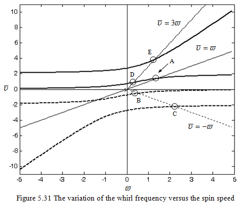
At this point the natural frequency is same as the spin speed of the rotor, it should be remembered that for the present case natural frequency is changing with the speed of the rotor due to gyroscopic effects. In Figure 5.14 a plot of these intersection points A for various values of the disc effect μ is plotted (with the assumption of the synchronous motion). This kind of disturbance is obviously excited by the unbalance, which gives the excitation in synchronous with the rotor speed. It is a resonance phenomenon and the vibration amplitude at this critical speed is proportional to the amount of unbalance. For the present case, it should be noted that ![]() =
= ![]() line does not intersect the second frequency curve, if we extend the line beyond point A. So there is no feasible second forward synchronous critical speed.
line does not intersect the second frequency curve, if we extend the line beyond point A. So there is no feasible second forward synchronous critical speed.
In Figure 5.31, frequency curves intersect the line ![]() = -
= -![]() at points B and C, which represent backward synchronous critical speeds. For this case the natural frequency is same as the rotor spin speed, however the sense is in the opposite direction. Such backward critical speeds are very rare to occur in practice, however, it is found to occur when there is a rotor-to-stator contact take place which gives excitation opposite to the rotation of the shaft due to the friction. It should be noted that in a general case, maximum of two such critical speeds might occur both for the forward and backward whirls (however, for the present case 1F and 2B). Apart from these synchronous critical whirls if the rotor has excitation which is for example thrice the spin speed then corresponding critical speeds can be obtained by intersection of a line
at points B and C, which represent backward synchronous critical speeds. For this case the natural frequency is same as the rotor spin speed, however the sense is in the opposite direction. Such backward critical speeds are very rare to occur in practice, however, it is found to occur when there is a rotor-to-stator contact take place which gives excitation opposite to the rotation of the shaft due to the friction. It should be noted that in a general case, maximum of two such critical speeds might occur both for the forward and backward whirls (however, for the present case 1F and 2B). Apart from these synchronous critical whirls if the rotor has excitation which is for example thrice the spin speed then corresponding critical speeds can be obtained by intersection of a line ![]() = 3
= 3![]() with the frequency curve, i.e. at points D and E. However, occurrence of such critical speeds is very rare since to excite such critical speeds physically such excitation mechanism should be present and most of the cases they are not dangerous i.e. the amplitude of vibrations are low. Coordinates of various points in Fig. 5.31 are: A(1.414, 1.414), B(0.0513, -0.513), C(2.252, -2.252), D(0.2916, 0.8882), E(1.3, 3.9002).
with the frequency curve, i.e. at points D and E. However, occurrence of such critical speeds is very rare since to excite such critical speeds physically such excitation mechanism should be present and most of the cases they are not dangerous i.e. the amplitude of vibrations are low. Coordinates of various points in Fig. 5.31 are: A(1.414, 1.414), B(0.0513, -0.513), C(2.252, -2.252), D(0.2916, 0.8882), E(1.3, 3.9002).
The summary of the quasi-static analysis of a single mass system with gyroscopic effects are presented as follows.
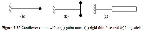
Case I: Forv = ω, i.e. the synchronous whirl, a single forward critical speed is obtained for three cases as shown in Figure 5.32 based on the centrifugal force concept.
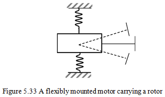
Case II: For a rotor mounted on flexible torsional springs as shown in Figure 5.33, it has two kinds of whirls: fast whirl (forward) in same sense as ω, and slow whirl (backward) in opposite sense as w. This is analysed based on the change in the angular momentum principle.
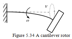
Case III: For a general motion of a cantilever rotor as shown in Figure 5.34, it has four whirl natural frequencies with two forward and two backward. One of the forward critical speeds is same as for the case I due the unbalance in the rotor. This is also analysed based on the change in the angular momentum principle.
Example 5.4 Obtain the transverse forward and backward synchronous critical speeds for a general motion of a rotor system as shown in Figure 5.35. Take the mass of the disc, m = 10 kg, the diametral mass moment of inertia, Id = 0.02 kg-m2 and the polar mass moment of inertia, Ip = 0.04 kg-m2. The disc is placed at b = 0.25 m from the right support. The shaft has the diameter of 10 mm, the total span length of 1 m and the Young’s modulus of 2.1 X 10¹¹ N/m2. The shaft is assumed to be massless and consider gyroscopic effects.
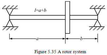
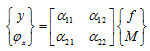
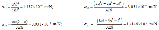
Solution: For rotor system shown in Figure 5.35, influence coefficients are defined as:
With
From equation (5.72), the frequency equation is given by
(a) |
we have
![]()
and
![]()
On substituting values of μ and ![]() in equation (a), we get
in equation (a), we get
(b) |